
The first tests done when machine arrived at the workshop discovered an issue on the geometry of the ram —Y axis—. The ram has a sensible play in some positions that can be measured when moving it on the Y axis. This will be one of the most interesting problems to repair during this rebuilding.
The test done some time ago was registered on the next video:
You can see how the ram have an horizontal displacement of about 0,03 mm when you change the direction. This suggests that there is some wear on the guides (or other kind of problem).
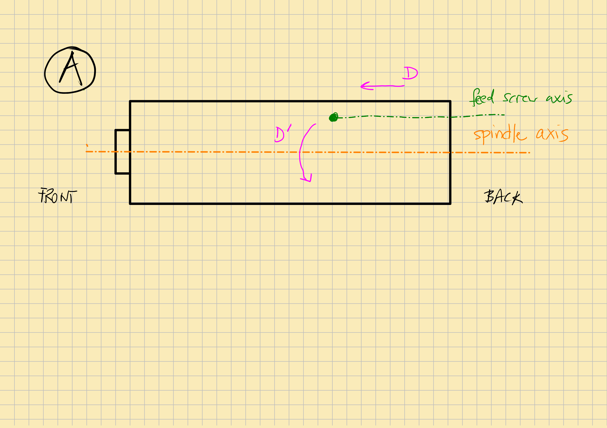
To better undestand this, you should know that the feedscrew that moves the ram is assymetric and thus pushes and pulls in an eccentrical way, inducing a small torque on the ram that explains this movement. It would be arguable if this design is the best one.
The next sketch (A) illustrates this. It represents a top view of the ram. Note that the ram axis (spindle axis) isn’t the same as the feed screw axis. Thus, when you push the ram in direction D using the screw the torque induced rotates the ram in the direction D’. Because of this, when you change the displacement direction of the ram a rocking movement appears that reveals the play of the guides. This is what is observed on the last video.
To face this issue I proceed by first making a good diagnosis of the problem, then understanding how to solve and finally solve it.
Clean the guides
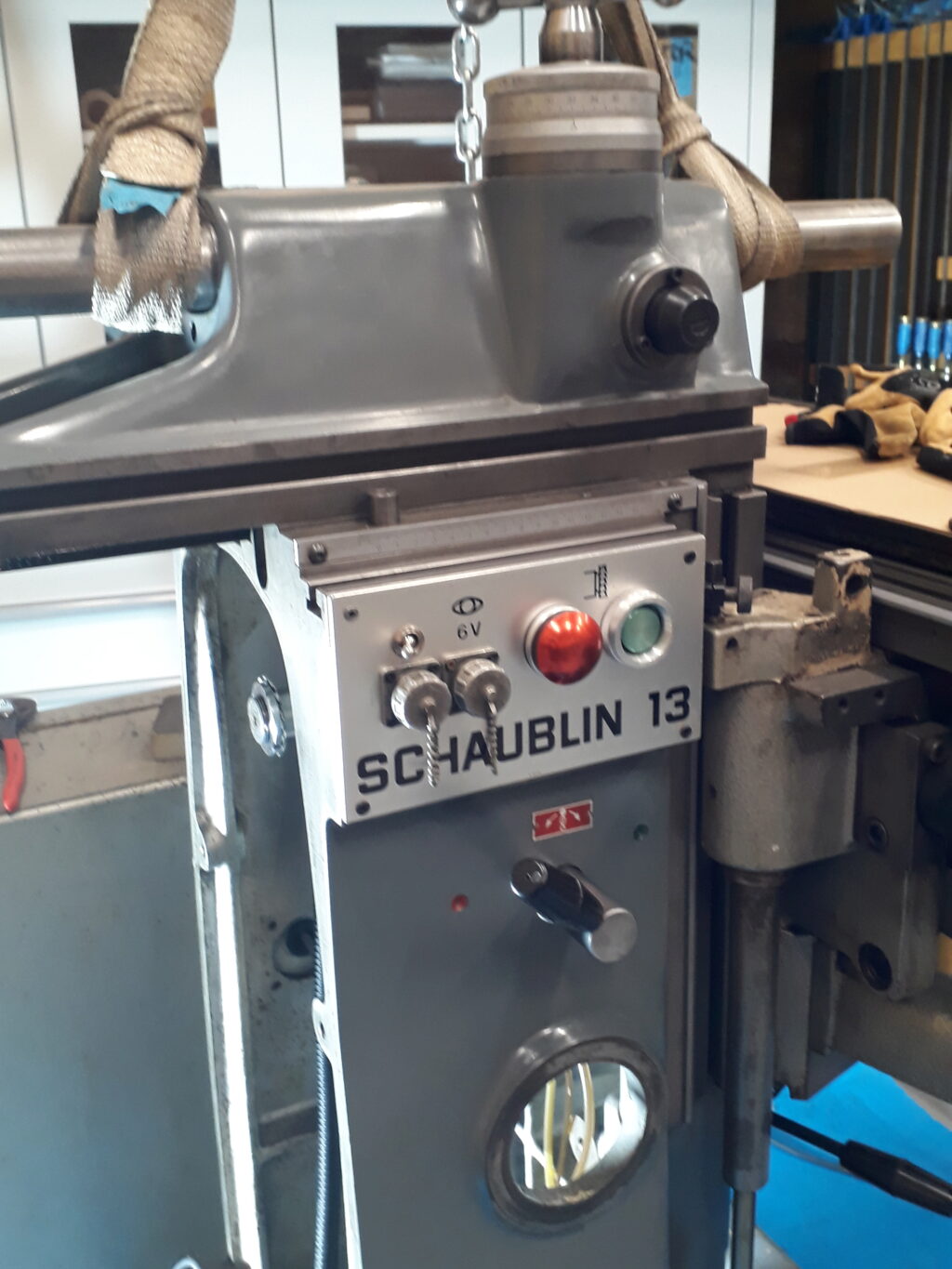
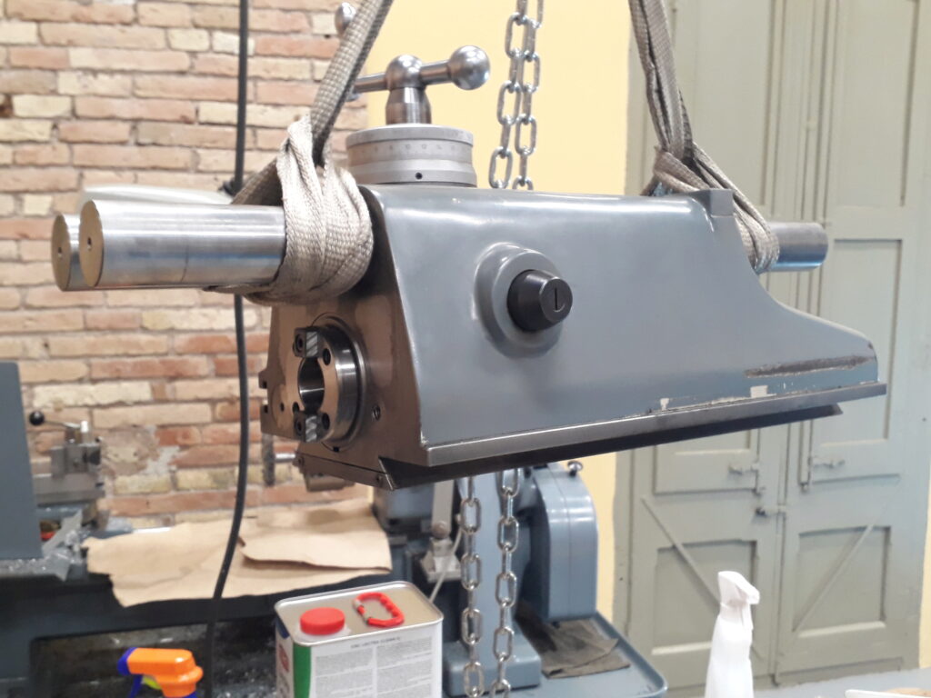
I first I wanted to discard that there is no trivial issue like some kind of dirt in the guides. Then I pulled apart the ram. This is a delicate work because you should be carefull not to destroy the gasket with the spindle gear. I used the crane as shown in this picture:
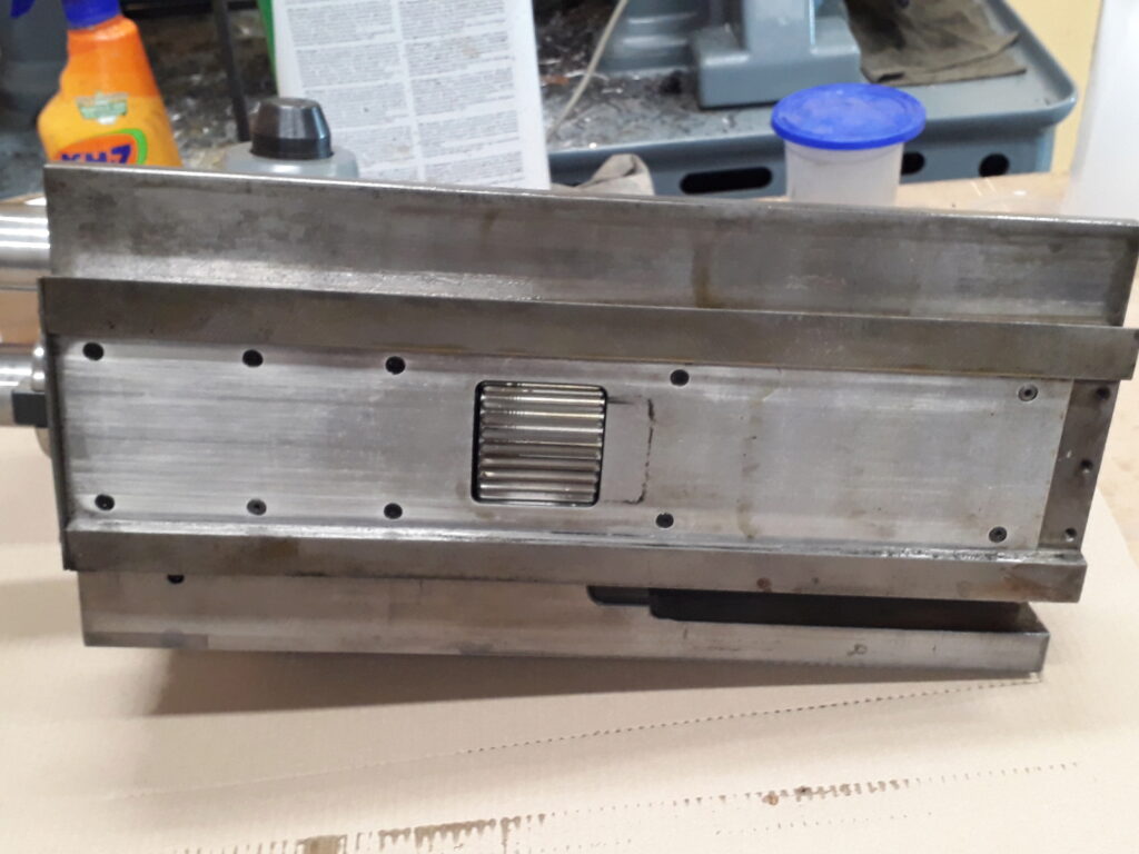
If you dismantle the locking handle and pull out the gib, the ram can be pushed to the front and then, lifting it with care, it goes over the leather gasket of the power gear. What follows is a picture of the ram after being surpased the gasquet.
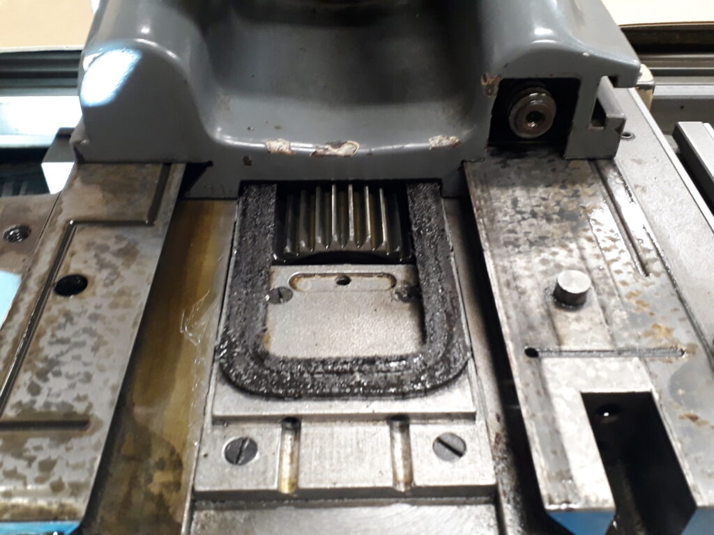
Note the scraping pattern on top of static part of the guides, the leather gasket and the driver gear.
Then the ram is moved to the worktable, inspected and carefully cleaned. No kind of dirt or scratch is found in the guides. Interesting to note, the ram guides are left grinded while the static part of the guides are manually adjusted by scraping.
The cleaned parts are mounted again. I found an interesting trick to protect the gasket when the spindle gear surpases it: protect the gasket with a piece of rigid plastic sheet —like the one used to work chocolate— and when ram is in place again pull the sheet. I’m refering to a material like this one.
Test again the play
Having found nothing disturbing the guides, after mounting the ram again the have not vanished. Then, next step was to measure carefully this play. I would say that this play is heavily influenced by the gib position but that pushing the gib until you feel an uncomfortable displacement, do not eliminates the play. To take the measures the gib was adjusted for a smooth operation in all the ram travel, avoiding hard points.
The ram travel was divided in 20mm sections and marked on the ram. A number of tests were conduced in each section giving a complete picture of the play. Next I describe the tests and the results obtained.
Test1: rocking of the ram in vertical plane
The test measures the play in the vertical plane of the ram. The ram is hand forced up and down while measuring the play as shown in this picture:
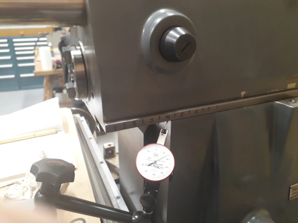
The result measured in every section (see the last picture where the sections are marked on the ram) is as follows:
| Section | 1 | 2 | 3 | 4 | 5 | 6 | 7 |
|---|---|---|---|---|---|---|---|
| Play (µm) | 3 | 4 | 3 | 7 | 8 | 8 | 7 |
Test2: rocking of the ram in horizontal plane
The test measures the play in the horizontal plane of the ram. The ram is hand forced left and right while measuring the play at 150mm of the ram face.
The result measured in every section is as follows:
| Section | 1 | 2 | 3 | 4 | 5 | 6 | 7 |
|---|---|---|---|---|---|---|---|
| Play (µm) | 10 | 16 | 22 | 54 | 68 | 50 | 34 |
Test3: rocking of the ram in horizontal plane
The test measures the play in the horizontal plane of the ram. The ram is hand forced left and right while measuring the play just as shown on the next picture:
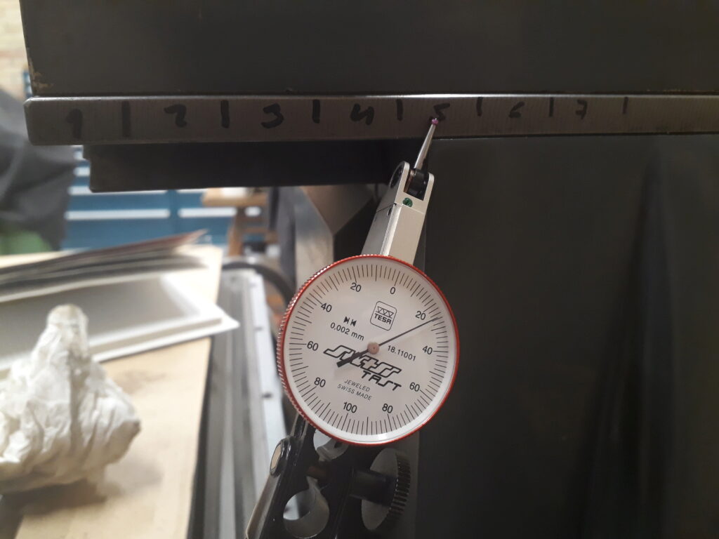
The result measured in every section is as follows:
| Section | 1 | 2 | 3 | 4 | 5 | 6 | 7 |
|---|---|---|---|---|---|---|---|
| Play (µm) | 6 | 9 | 21 | 34 | 50 | 42 | 20 |
Test4: rocking of the ram in horizontal plane
The test measures the play in the horizontal plane of the ram. The ram is hand forced left and right while measuring the play in the back just as shown on the next picture:
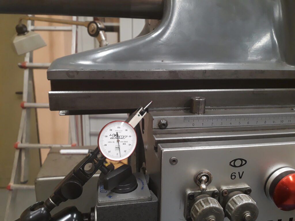
The result measured in every section is as follows:
| Section | 1 | 2 | 3 | 4 | 5 | 6 | 7 |
|---|---|---|---|---|---|---|---|
| Play (µm) | 5 | 5 | 8 | 10 | 8 | 9 | 7 |
Test chart
In addition to the previous tests, the set of tests related to the headstock and table were carried away. As a reference, a test chart for an Aciera 3 was used —both machines are of similar size and quality. The results are annotated in this test chart. You can see that the machine but the headstock is in a nice condition.
Caveat lector: acceptance tests are only a partial information, mainly about machine geometry.
Conclusions
- Given teh condition of the rest of the machine, it seems appropiate to spend efforts on repairing the ram.
- The tests show an amount of wear on the ram guides, mainly in sections 3-6. Section 1 exhibits the minimal wear. This is consistent with an ordinary use of the ram.
- The front side shows more play than the front side.
- It is not clear where the wear is: in the male guide, in the female or in both of them.
- It is fascinating why the wear appears mainly on the headstock and not on the other machine slides.