The Schaublin 13 longitudinal slide geometry was checked and its ways overhauled. This post explains how it was done.
Analise the wear
The first ocular inspection of the slide evidenced that there is not too much wear on it. Most of the flats reveal consistent grinding marks as shown in the next picture:
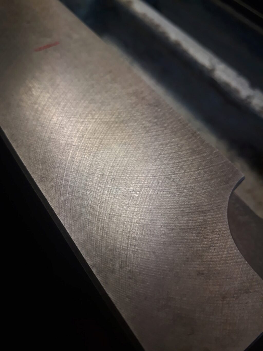
This pattern of grinding was of most interest. It seems that replaced the traditionally scraped surfaces on many high quality machines of after 1970’s. In a discusion with Oriol Morató (https://www.instagram.com/mecanicadeprecisio) we guessed that it is achieved by a fine grinding that lefts a geometrically right and smooth face followed by a controlled rough grinding that prints the characteristic pattern seen in the picture while maintaining the geometry. In our opinion the rough grinding scratches act as an oil reservoir. This technique gives to the surface properties like these of scraped surfaces. Maybe there is some reader which can confirm or reject this issue.
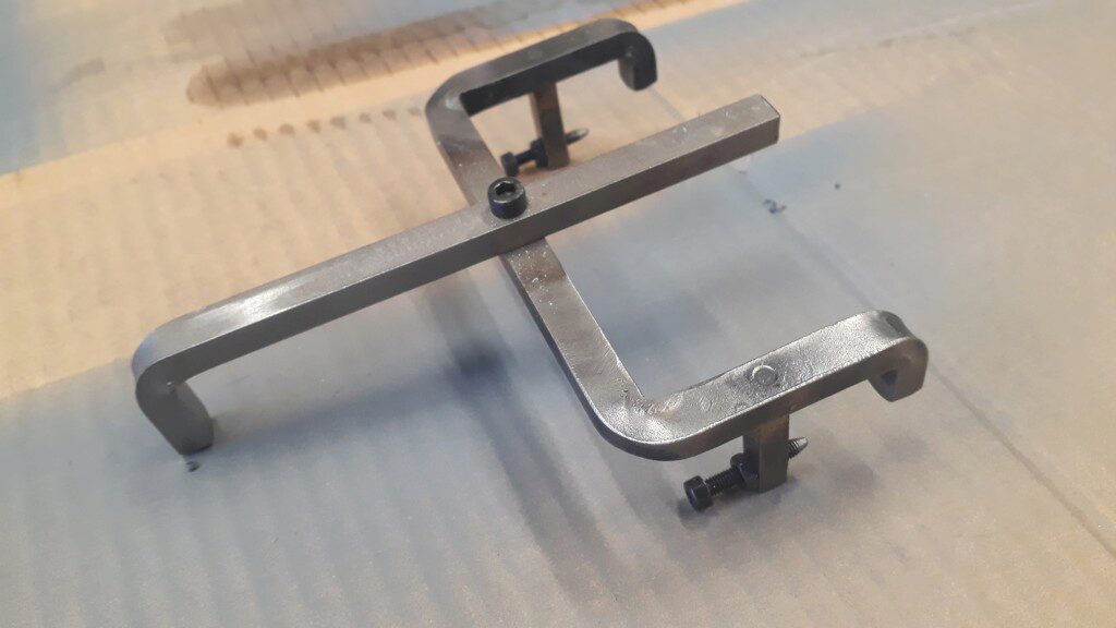
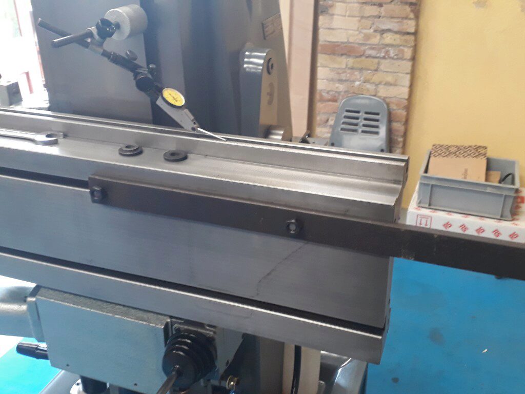
Internal faces are not so easy to look at, but a test with the straight edge reveals the wear is very slight. Also testing the paralelism with the indicator and the jig shown on next picture results in a mostly paralel faces.
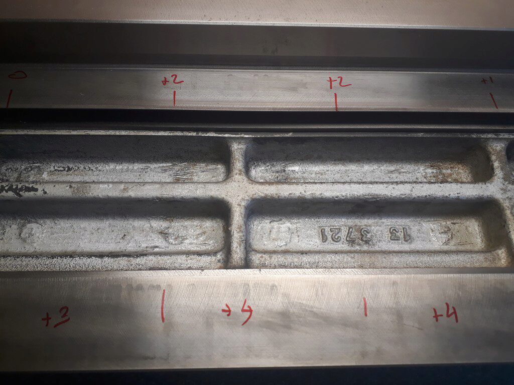
The last test done was to check the paralelism between the working face of the slide and the ways. This was done by laying the slide on the precision surface as you can see on the picture below.
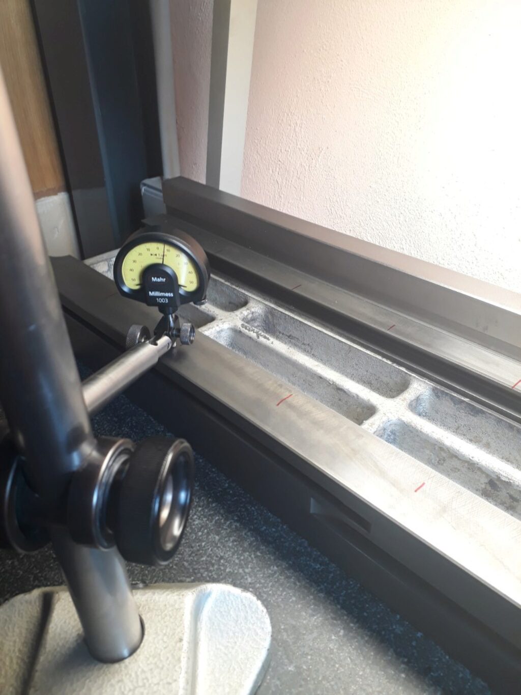
This test concluded that working face and ways are paralel. It also discovered that the top slide is more or less 3µm lower. This is consistent with the preferred inclination of the milling machine working table: slightly higher on the front side, to compensate for the load of the tooling it supports.
With all the info I decided to be conservative and not work on the longitudinal slide. If necessary, it is easy to put aside and work on it in the future.
Another matter where the fixed ways on the apron that support the slide. In this case a simple test with the stright edge reveals a sensible wear on the top one. On the bottom one there is the gib, that I assumed it is also weared. The wear pattern is more pronounced on the extremes, which is reasonable.
I first focused on the top way. Inspecting it carefully the wear pattern is more pronounced on the sides and, at the same time, on the top side of the way. The following drawing sketches this pattern. In this drawing, the green hatched zone shows the weared zone of the fixed top way.
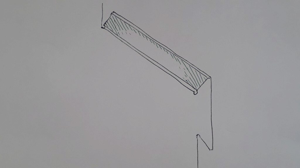
This pattern is consistent with the loads of the usual work.
To further understand how loads are related to wear, look at the following drawings.
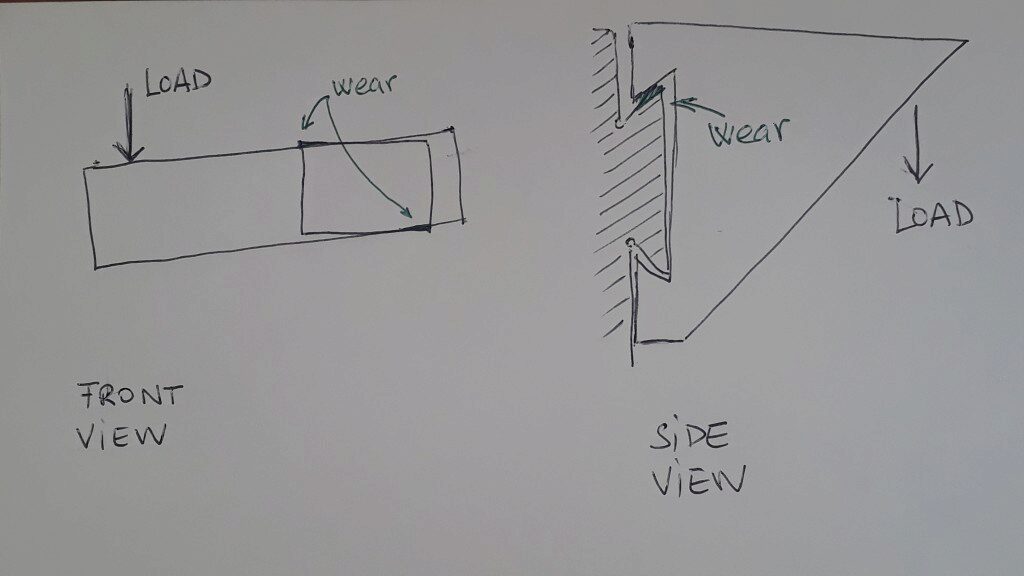
On the left (front view) the small rectangle represents the steady ways of the longitudinal slide. The longitudinal slide itself is drawn as the long rectangle. Because load on the table (including the table itself) is usually uncentered the fixed ways used to wear on the corners as shown in green. On the right drawing (side view) it is shown the table + slide + steady way assembly. The load and the table weight have a tendency to wear on the top part of the steady way, as shown in green.
Repair the wear
To repair the wear I began by scraping the top steady way. The main help was the straigh edge. I’ve been carefull to not change the orthogonality of the way respect the Z slide. Checking this squareness directly over the way is not easy.
Once the top guide recovered its flattness, I turned the work to the gib. The gib is the contact face of the bottom part of the way. Scraping the gib is not easy because there is no reference. Usually the gibs are slightly bent and only when they are in its seat have the real geometry. In this case I relied on measuring the rocking of the slide using this simple lever bolted to the slide.
The indicator measure the rocking of the slide. I used my own weight to force the table simulating a real load. With this, is easy to perceive the flatness of the gib once the top way is scraped. I scraped until a rocking under 10µm (maybe around 7 or 5) is achieved. It should be said that under that heavy load (my own weight plus the lever amplification), the oil surface is also stretched. This should be taken into account when measuring.
The flat parts of the steady ways where no modified. The inspection showed not too much wear and thus I decided to be conservative. The small faces of the dovetail ways where scraped a bit hollow on the center. I will write about this detail in a future post however.
Assembling again
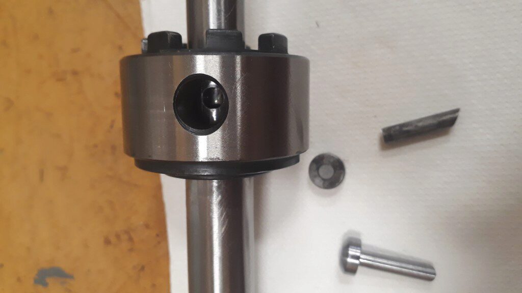
After the repair work, all the slide parts were assembled again. Left and right dials mechanism were completely cleaned, the bearings newly lubricated with «Kluber LDS Special A» grease and assembled again. During the disassembling process the right dial, the locking pin revealed broken. I had to mak a new one with the same radious anb heat treat it. Last pictures shows it. I will explain in a future post how the radius was turned.