This post shows the kind of works that can be done with a Kaiser Piccolo boring head. It includes the usual boring work but also the facing work usind the automatic travel of the head and an example of peg turning. The usual boring head tooling is also reviewed.
The boring head parts

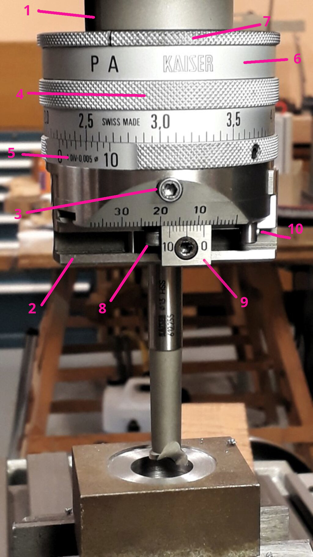
Boring head and its parts
These are the main parts of the boring head (see the previous figure).
- The shank.
- The slide, that moves across the diameter of the head and has a number of holes to attach the tools.
- The locking screw. It locks the slide to avoid traveling.
- The travel ring. It displaces the ring and it is marked in 0,05 mm steps.
- The vernier scale. This ring can be moved to set the “O” of the displacement ring. A set screw frees it to rotate. Additionally, it allows to read displacements of 0,005 mm by using the vernier marks.
- The holding ring. This ring has a hole were the steady bar can be used to avoid it rotating. The part that holds the bar works as a switch that runs back the slide.
- The P-A disk. This is used to select the head function: A for boring and P for facing counterbores. Can be switched easily by hand if the holding device is the right position. You will discover the position by trying.
- The return stop. It is used to stop the slide during the return travel.
- The forward stop. It is used to limit the forward travel of the slide and, thus, it sets the max cutting diameter when facing.
- The control pin. It makes easier to check if the forward travel has traveled to the limit set up by the forward stop.
The slide has three vertical holes of 10mm and an horizontal one. They are used to attach the tooling. Slide runs to the left (try it by moving the travel ring by increasing the marked numbers).
Dimensions and working limits
- Shank turns clockwise
- Facing and boring from 2mm to 180mm
- Max slide travel 30mm
- Radial slide feed per revolution 0,05mm
- Slide fast backwards per revolution 2,5mm
- Slide min feed 0,05mm (0,005mm reading on the vernier)
- Tools shank diameter 10mm
Boring holes
Boring work is done with the P-A disk in position A. Simply attach the right tool (depending if it is a through bore or not) and adjust the slide to “0” by moving the slide till the tool is on the hole wall. Move the vernier ring to the zero position to have a reference. Just move the travel ring in the increasing way by the cutting depth you need and bore it. Remember to lock the slide using the locking screw before begin ti cut. This adds rigidity and avoids premature wear. Be aware of managing the backlash in a proper way. Repeat until the desired diameter is achieved.
Notice that the tool should be attached to a right hole. The hint is to remember that the slide travels at most about 30mm.
Additionally, you can set the vernier ring in such a way that “0” corresponds to the final diameter and work by cutting until the travel ring arrives to “0”. The end stop can also be useful if you are boring a batch of parts that can be attached in the same precise position. Just bore the first part to size and, when in the final position, move the end stop.
Facing or counterboring
For this work the slide moves automatically. At the same time the head turns, the slide travels continuously. This allows to cut a flat face around a hole (counterboring).
Because of the automatic traveling is much better to work using the stops. The procedure is the following:
- Attach the right tool.
- Free the locking screw of the slide.
- Move the slide until it is on the hole wall.
- Set the forward stop using the scale and vernier. What you read there is the maximum radius travel of the slide. Then, the diameter of the counterbore will be twice what is read in the scale.
- Move the slide back a bit just to free the tool. Set the back stop. This will stop the slide when doing the fast back travel.
- Move down the head the cutting depth amount.
- Now things are ready to begin cutting.
- Start the head rotation
- Stop the retaining ring with the hand. As it turns free, it is not an issue.
- Insert the stick to retain the holding ring. You will not appreciate too much presure due to head gearing.
- Move the A-P disk to P position. You should find the right position for the stick holder.
- The slide begins to travel slowly in the sense of increasing travel ring numbers. Soon it will begin cuttind the face.
- When it reaches the forward stop, a pressure clutch will stop the slide travel. You should turn the A-P disk to the A position again. This stops the automatic traveling. You can do this without stopping the head. Is important to move the disk to A position soon to avoid damaging the clutch.
- It’s time to move the head to the initial position by using the fast back travel. Just move the hold stick to the back. The holding part rotates slightly and the back travel activated.
- The slide goes back very fast untill de back stop is reached. A natural movement of the stick stops the back travel.
- Without stoping the head, you can give more cutting depth and begin the cycle again until done.
The same procedure can be used to deep counterbore, to make a hole bottom flat or to cut a recess inside the hole.
Sometimes, it’s difficult to appreciate if a cut arrived to the end. Specially, when the cut is done deep in the hole. The head provides a clever jig for testing whether the slide arrived at the stop or, by some reason, the friction clutch was stopped it before. Push the small control pin to the left. When the slide approaches the end of travel the pin will be pushed by the stop. After sliding back the tool, you can check if the slide traveled to end.
Turning pegs
The boring head can also be used to turn pegs on the milling machine. Sometimes this can be advantadgeous when parts have complex shapes. Next video shows the Kaiser Piccolo in a peg turning work on a Schaublin 13. Head descent is driven by hand using the slow motion feed of the milling head.
Tooling
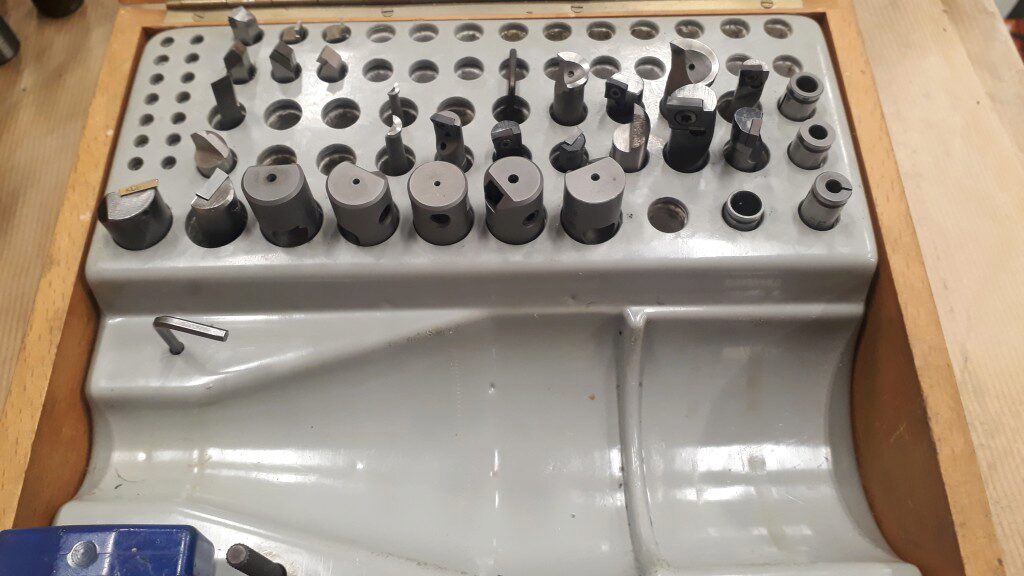
The Kaiser Piccolo comes with a wood box to store the head, the keys and the tooling. The picture below shows it.

Boring head storage box and tooling
The tooling comprises:
- A set of indexable tools for boring and for facing of different sizes.
- A set of HSS tools for bring and facing, some of them for small diameter bores.
- Some tools for chamfering the holes.
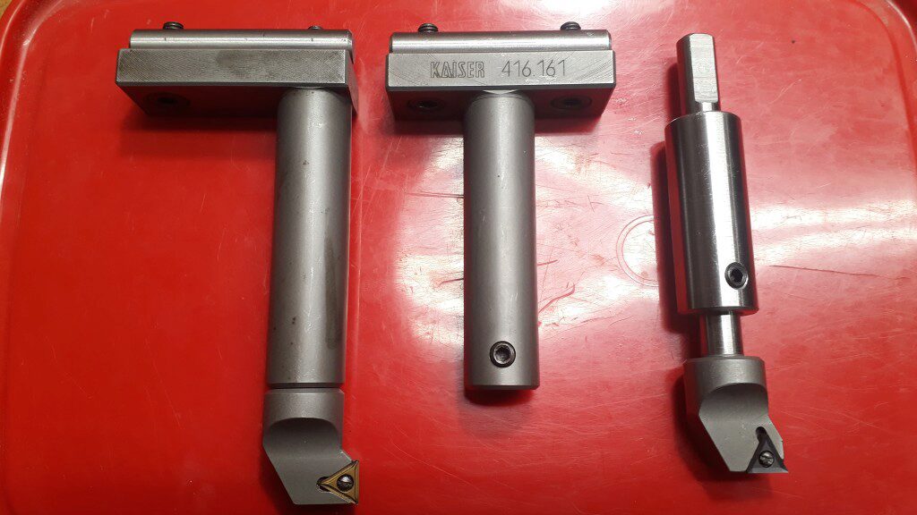
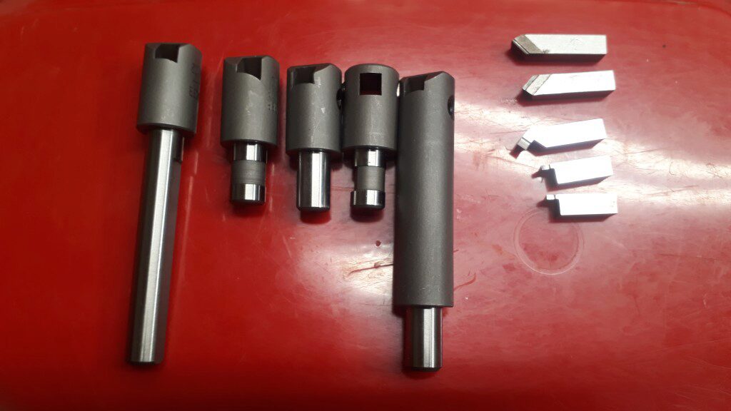
- A set of square (6x6mm) tools holders. This includes some extension tubes to work in deep conditions.
- Some square (6x6mm) HSS and HM tools. Including some recessing tools.
- A set of reduction bushes for small cylindrical shank cutters
The following pictures show some of these tools and toolholders.

Extension toolholders and indexable tools

