
The Kaiser Piccolo is an exquisitely made mid sized boring head with boring and automatic facing functions. I got a ISO30 one in a very nice condition together with a bunch of tooling. When tested it performed very fine but I couldn’t switch easily between facing and boring (marked as P and A in the head, maybe for the french «planage» and «alésage»). It needs to be serviced to cope with this jam.
Table of Contents
The Kaiser Piccolo boring head
The Kaiser boring head is a middle size boring head with a facing and boring range from 2mm to 180mm. The slide travel is about 30mm maximum. It has three functions:
- boring, with a minimum diameter adjusting step of 0,005 mm
- facing, where the slide has an automatic feed of 0,05 mm per revolution
- fast slide return, where the slide return automatically at 2,5mm per revolution
The head has a friction clutch that limits the slide and allows the slide displacement be limited by stops.
I know of two versions of the head. The old version could be easily recognized by its small rotary switch between boring and facing functions. I own a new version one with an STP shank. This is a Kaiser specific shank used as an interface to other standard shanks. In this case it mounts an ISO 30 shank.
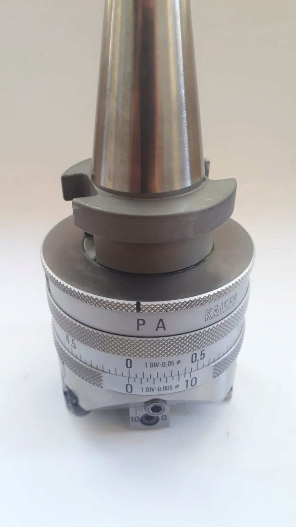
A picture of the Kaiser Piccolo boring head
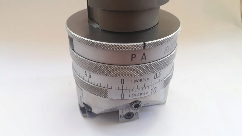
Detail of the Kaiser Piccolo boring head
The Boring Head P-A Switch is Locked
My boring head looks like the P-A switching ring is locked into A position. That’s suprising because the head is nicely used and seems not abused at all. However, after fighting with the ring during days the result is clear: the ring is locked.
The head should be serviced to solve this lock.
How to Take Kaiser Piccolo Apart?
The first challenge is to take apart the head. After a search in some forums and a fruitful talk with Charles, the mistery was discovered: head should be taken apart by untighting a special flat nut that is on top of the head.
First, then, the ISO 30 shank should be removed from the STP taper. This is easy to do by just tightening the ISO 30 shank in the vice and unscrewing all the head. It’s useful to slightly heat the ISO 30 shank. Take an adjusting wrench of a nice size and adjust it to the head slide. Unscrew counterclockwise. It is tight, but a large enough wrench will do the job.
Under the ISO 30 adaptor will appear a flat nut with three small holes. This is the nut that frees all the boring head interior parts. The holes are filled with a pin that retain the nut on the part below. These pins should be completelly drilled and removed. You will need an extralarge drill or an home made extension.

Drilling the boring head nut pins
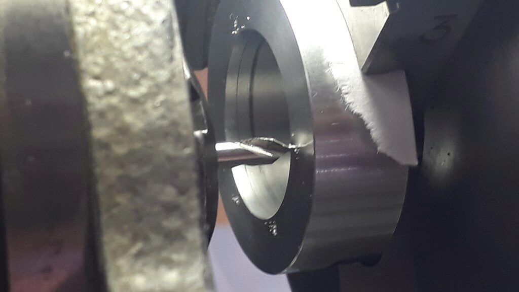
The boring diameter is 1,5mm and should be drilled about 6mm depth. Sometimes, a smaller diameter drill of about 1,25mm could be useful too. The objective is to completely remove the pins. You will feel when the drill impacts on the hard part in the bottom. Be gentle with this and try not to mark the bottom part with the drill.
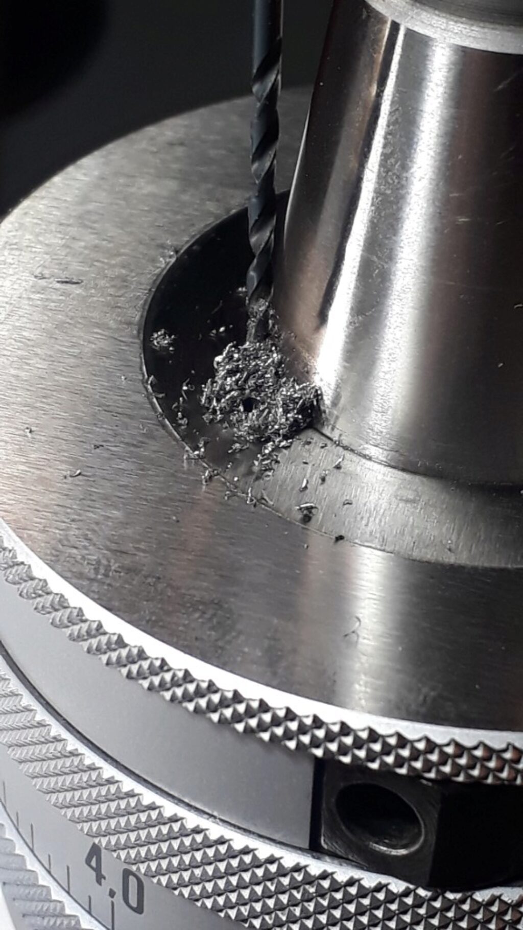
Detail of a pin drilling process
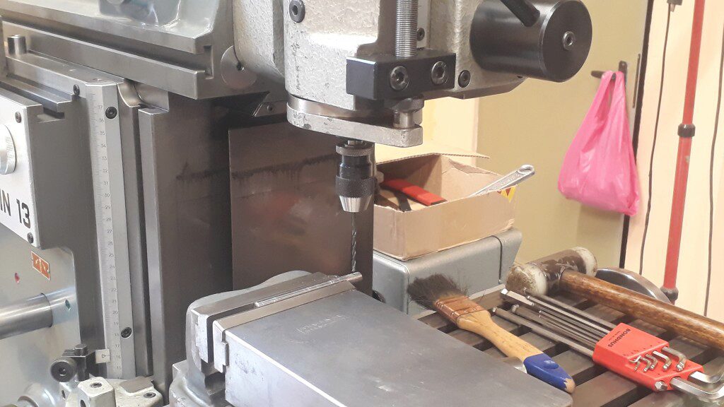
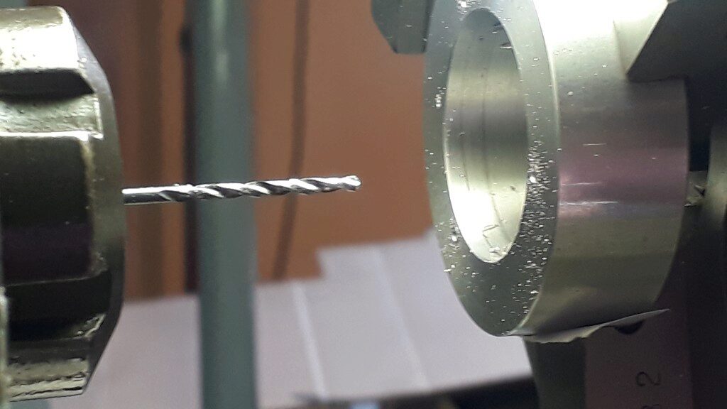
Working a drill extension in the milling machine
Make the Special Pin Wrench
Once pins are removed, you will need a special wrench to unscrew it. I made one from an aluminium ring and some cuts of clockmaker blue steel (tamponstahl).
First step is to measure the precise holes position. If you assume that they are in the same circle and that all of them are at an angle of 120 degrees, you only need to measure the distance between holes. Using a couple of drills as reference pins the distance could be measured with a caliper or a micrometer. After that, a bit of trigonometry will do the job.
Measuring the distance between holes using drills
Calculation of special wrench main distances
The result is that the centers of the pin holes are on a 30mm circle centered on the head shaft. With this in mind, I turned a kind of thick ring of aluminium. On this, three 1,5mm where drilled through using a divider on the Schaublin 13.
Align the part center using the Diacator alignment gauge
A detail of the alignment process
Spot the drilling points of the wrench
Drill the wrench pin holes
Once the ring is drilled, cut some long pins of clockmaker’s blue steel of 1,5mm. This kind of small steel bars used by clockmakers is of good quality, easy to find in small batches and hardened at an interesting level: it is hard but can be worked well enough. Pins need to protrude the ring about 4mm. They could be fixed in the ring with a bit of cyanoacrylate glue.
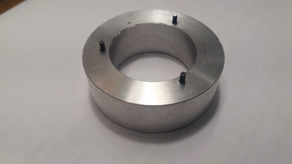
The special wrench for Kaiser Piccolo (nut side)
If the wrench fits the nut, drill on the oposite side some 4mm holes to be turned with a standard pin wrench. Next picture shows it. Remember that pin wrench should then’t be in contact with the STP cone of the head.
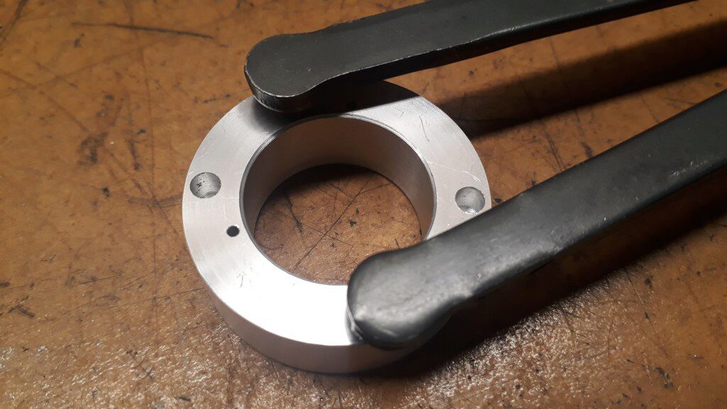
The special wrench for Kaiser Piccolo (top side)
Take Apart the Boring Head
Now the Kaiser Piccolo head can be taken apart. It is usefull to mark the original position of the nut to be tightened appropiately when mounted again. Then, just grip it on the vice and unscrew slighty the top nut until can be turned by hand.
Do not unscrew the nut completely! Inside the head there are a couple of ball bearings that will fall off when you unscrew it.
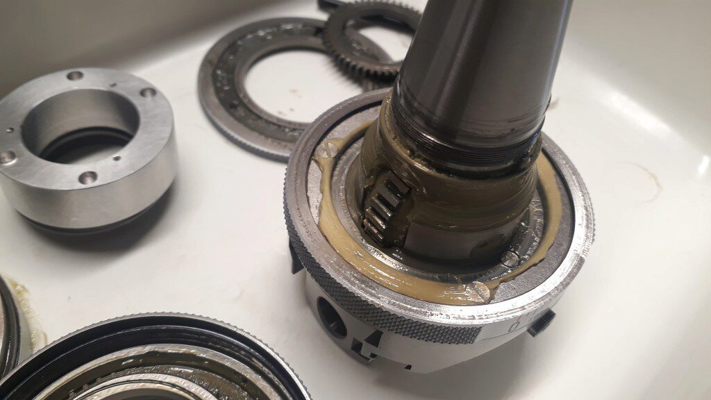
It’s very interesting to work on the head maintaining it in a plastic container that avoids losing balls. With this care, just unscrew the nut and the head rings will be freeded and the top bearing will appear. Preserve the steel balls in a secure container using tweezers. There are 54 balls of 2mm.
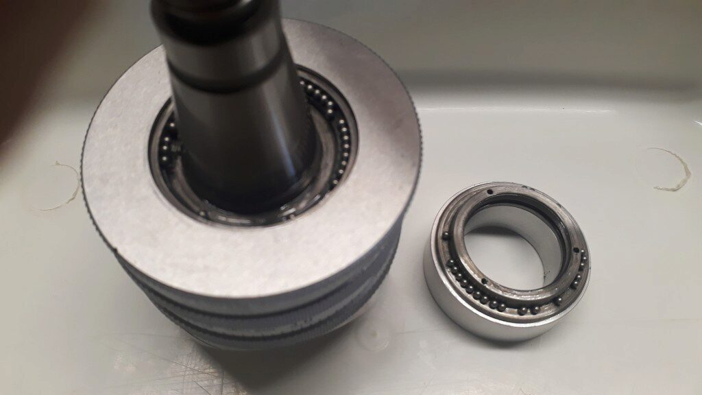
The unscrewed nut and the top bearing
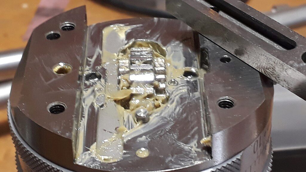
Once the top ring has been pulled apart, the top part of the second ring will appear. This is the ring that can be holded with a stick when working. Two distinct balls will appear. Both measure 2,5mm and are a bit greather than the bearing ones. The first one is a sliding ball on top of the clutch shaft (marked A) in the next figure. The second one is a spring and ball plunger that retains the top ring in a specific position (marked B).
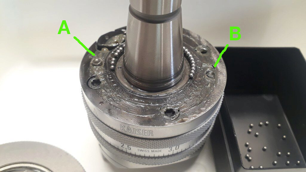
Top of second ring
Marked as (A) there is the clutch shaft. Marked as (B) is the top ring plunger spring.
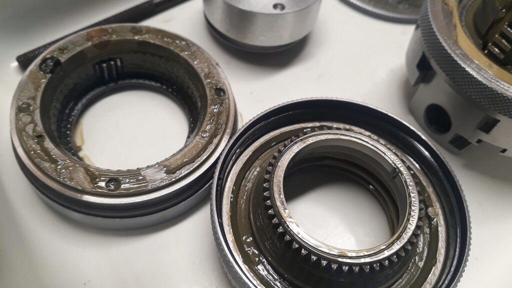
The second ring is easy to pull apart. Just pull it through the shank. You will discover the internal gears that move the slide in automatic mode. On the bottom of this ring there is the bottom ball bearing, be careful. This bearing is composed by 90 balls of 2mm.
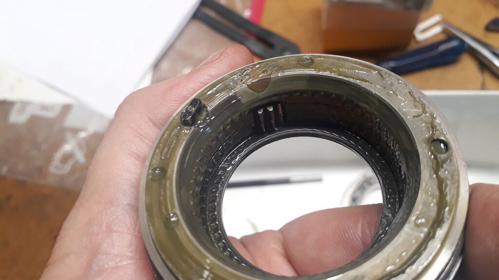
Bottom of the second ring
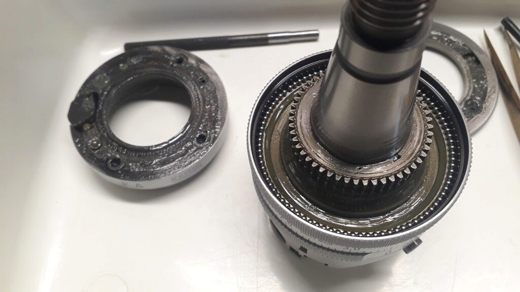
The head after pulling the second ring
In the left, there is the second ring. In the right you can see the bottom bearing and the two central gears. The top one is attached to the shaft by a small key. Note the small hole that is used to lock the top nut by inserting the pins. The bottom gear, barely visible under the top gear, is attached to the third ring and turns freely.
If you pull with care the third ring, you will discover the interior gear that rotates the main gear of the head. The main gear of the head displaces the slide. Look at the pictures below.
The third ring
In the interior you can apreciate an internal gear that engages the main gear. Main gear can be barely seen in top right.
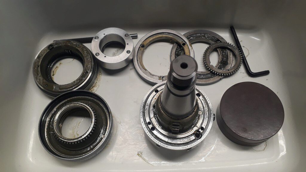
The Kaiser Piccolo fully dismantled
A detail of the main gear
This gear is moved by the third ring and it moves the head slide.
The main gear where it engages the head slide
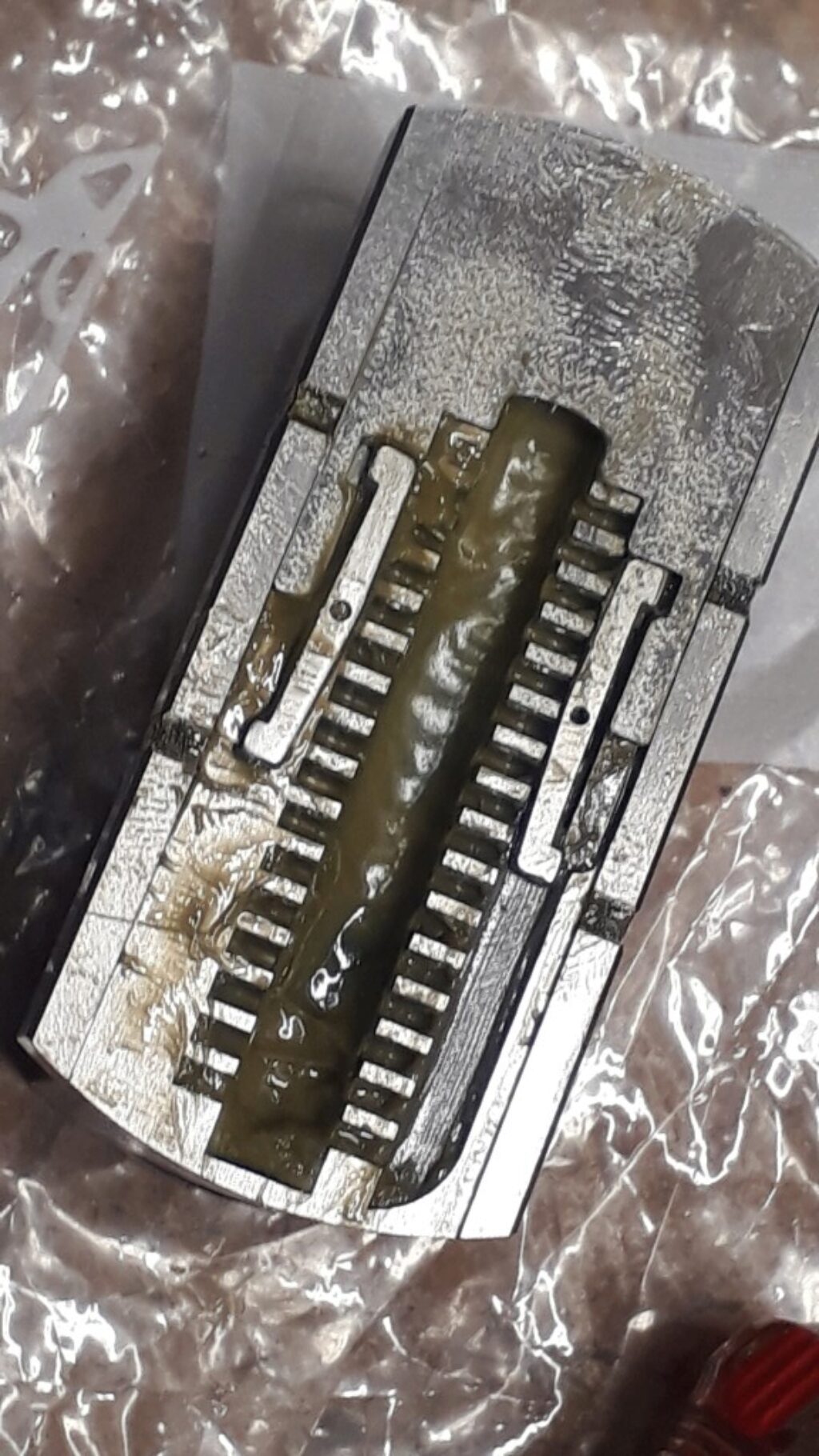
The hidden face of the slide where the main gear engages
Note that the main gear is composed by distinct diameter gears in the same assembly. Only the minor lateral gears move the slide. The major gear is moved by the third ring.
Solving the Kaiser Piccolo Jam
Finally, it is time to solve the boring head jam. After taking apart all the head I saw no problems that could explain the jam. I mounted it again and the head became locked again. I did the work of assembling and disassembling several times with the same result. At the end, I deduced that the locking effect should be produced by the plunger mechanism. The plunger ball has a diameter of 2,5mm while the spring hole measures 3,1mm. Seems to me the ball is displaced to a side of the hole when turning the top ring and it gets trapped in some way. That is weird because the ball seems to be the original one. I tested with a 3mm ball and all worked smooth as silk!
Remains the question about which is the right diameter for the plunger ball and, if 2,5mm is wrong, why is there a 2,5mm ball? Anyway, now it is working as expected.
All the rings and bearings were assembled again and the nut tightened to the mark we made before taking it apart. Then, a single pin is introduced in the single locking hole. The pin is made of brass to make easy drilling it again if needed.
How Does The Head Work
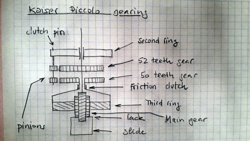
A sketch of the internal mechanisms of the Kaiser Piccolo
The main gear is a stepped gear. The exterior gears engage the rack of the head slide. Then when main gear turns, it moves the slide. The central part of the main gear engages the third ring internal gear. Both form a crossed gear system where one of the gears is an internal one. Thus, when you turn the third ring the internal gear force the main gear to rotate and the slide to move.
The two small pinions are on the same shaft but there is a clutch mechanism that allows them to turn independently or jointly. This clutch is actuated by the top ring (not shown in the drawing). When the top ring is in A position (boring) pinions are independent each other. However, when top ring is in P position (automatic facing) pinions are joined.
The 52 teeth gear is attached to the boring head shaft. Thus, in position P and the second ring steady in a position, when the shaft turns so does the pinion set. Because the third ring gear count 50 teeth, there is a differential action and, every turn of the head shaft the 50 teeth gear doesn’t turn a full revolution but a bit less: exactly 1/50 of revolution less. This means that the third ring has been displaced 1/50 of revolution. Hence, the slide has been displaced the proportional distance.
This big reduction effect allows a worker to fix the second ring with the retaining stick applying a slight pressure. At the same time, to avoid destroying the head, a friction clutch connects the 50 teeth gear with the internal gear of third ring. Instead of forcing too much the mechanism, if the slide becomes jammed, the friction clutch slides. This is also the effect of the stops in the boring head.
Interesting References
Some references that can be useful:
- Some PM with Charles (Demoniakteam at PassionUsinages), that helped me to understand how to take apart the head. https://passion-usinages.forumgratuit.org/t1399-tete-a-aleser-kaiser
- This post of Arnljot Seem https://www.instagram.com/p/B0V0FuWIZZy
- This thread on Metalworkforums https://metalworkforums.com/f65/t180755-disecting-imperial-majesty
- https://passion-usinages.forumgratuit.org/t9973-tete-a-aleser-kaiser-piccolo