
A look inside the drive train of this vintage Wörner drill press reveals a massive modification by a previous owner. To drastically reduce the rotation speeds, an extra intermediate pulley was spliced into the system, forcing a new single-step pulley onto the motor shaft. While it’s possible this was a custom factory job by Wörner, it’s far more likely a clever aftermarket hack. Either way, it’s coming off to make room for a more traditional setup.
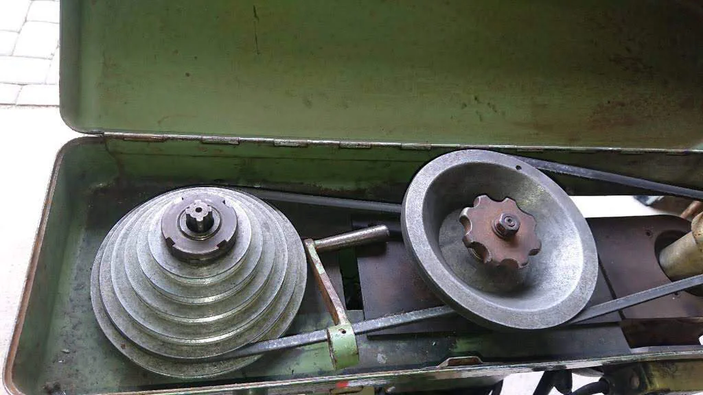
The old drive system with the double pulley setup. The crude handle used to lock the central pulley contrasts sharply with the sophisticated tension lever on the motor pulley.
I wanted to restore the original two-pulley drive system. I prefer this simpler arrangement, especially since the motor will be paired with a Variable Frequency Drive (VFD), providing full speed control.
The plan was to bore out the intermediate pulley and fit a new central core—machined from the current motor pulley—to match the motor shaft. I carefully measured the dimensions and drafted a few sketches.
Work began by carefully centering the pulley in the lathe before boring it out. Here are a few pictures of the process.
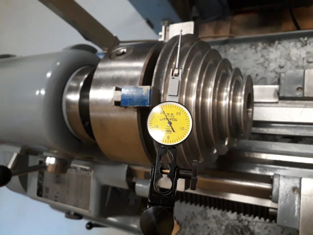
The central pulley was mounted in a four-jaw chuck and dialed in relative to the belt contact faces to prepare for boring.
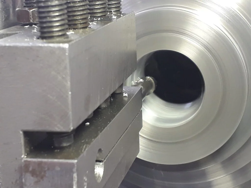
A view of the boring operation. I used a carbide-shank boring bar to prevent chatter.
Here is the finished pulley featuring a highly concentric bore. Note the clean surface finish with absolutely no chatter marks.
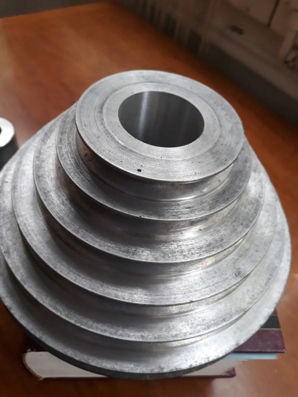
The completed boring job. Note the excellent surface quality of the bore.
The next step was to machine the core from the old motor drive pulley. The old pulley was first shortened in the chuck and then turned down while mounted on an expandable mandrel. The core’s outer diameter was left 0.01 mm oversized relative to the pulley bore to allow for a light shrink-fit. The pictures below document this process.
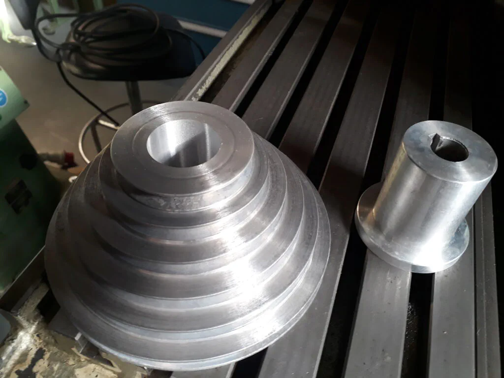
The finished step pulley and the core blank prior to turning it down to its final diameter.
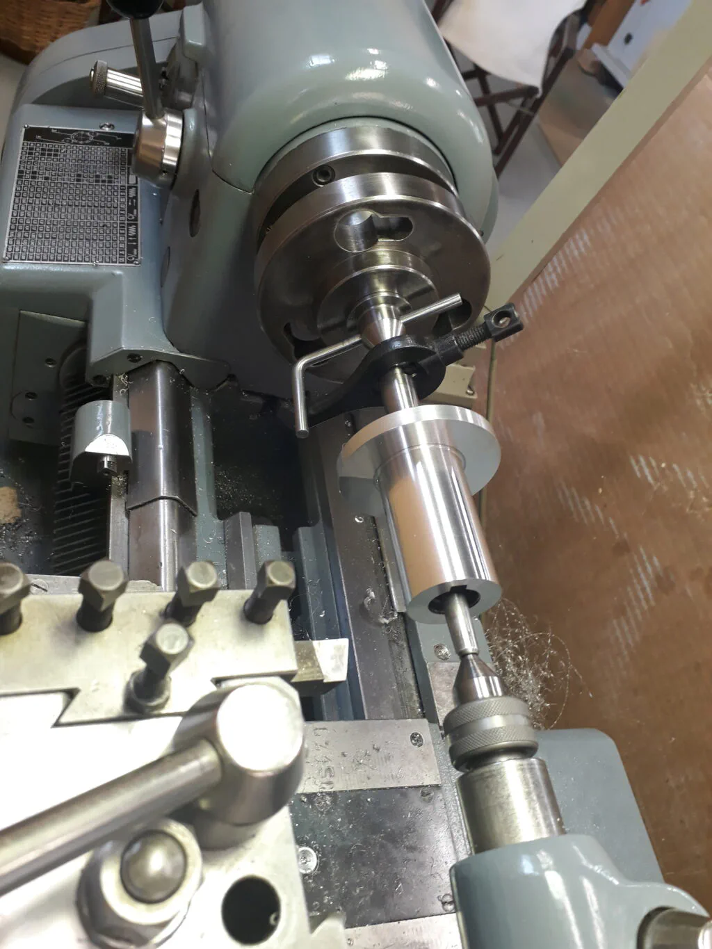
The pulley core mounted on an expandable mandrel with a lathe dog during the turning process.
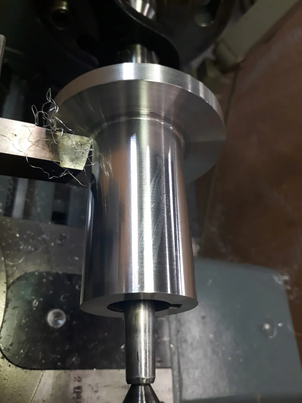
A close-up of the cutting process. I used a highly polished HSS tool with great results.
To finish the assembly, I marked out and drilled three holes for Allen screws to secure the core to the pulley. This was done using the milling machine’s dividing head, as shown below:
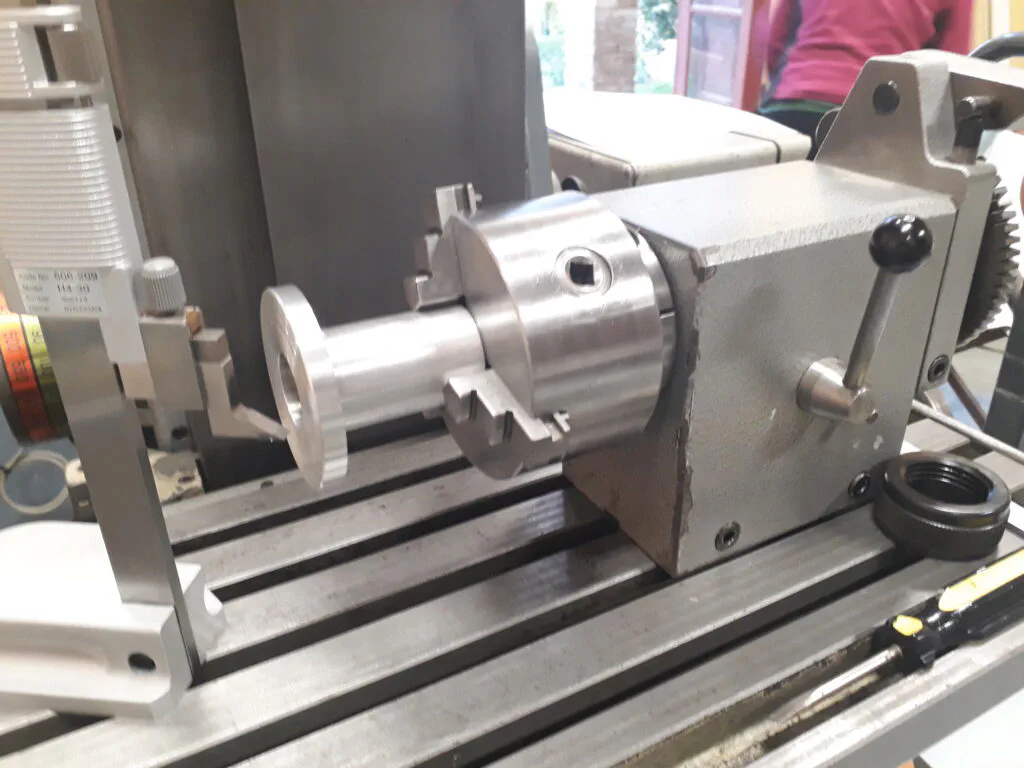
Marking out the hole locations using the milling machine’s dividing head and a surface gauge.
With the three holes drilled, here are the finished pulley and its new core right before assembly:
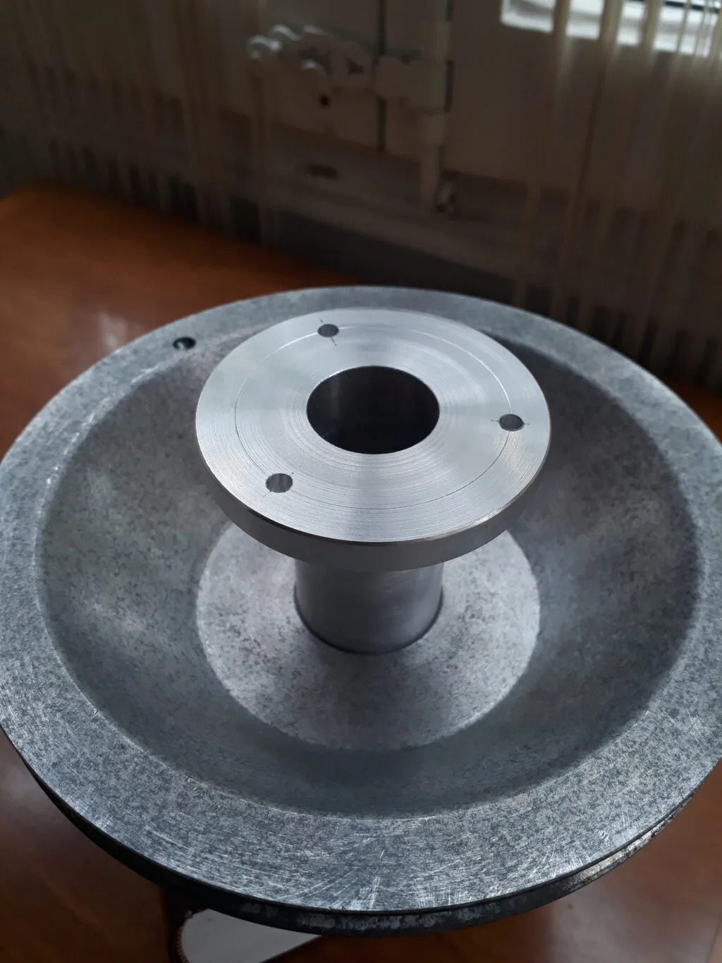
The step pulley and the finished core ready to be mated.
The core was shrink-fitted by heating the pulley with a hot air gun and pressing the core into place, using a light coat of anti-seize grease. Here is the final result:
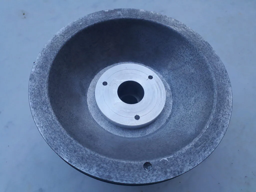
Top view of the completed pulley assembly showing the newly fitted core. The retaining screws have not yet been installed.
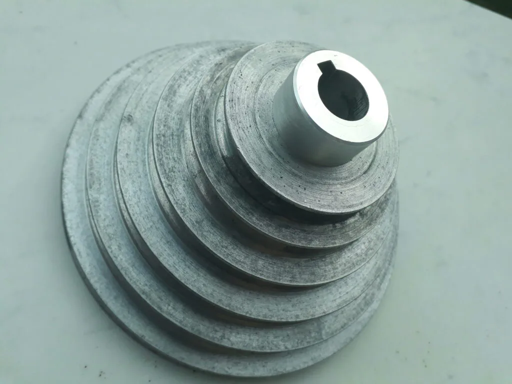
A bottom view of the pulley assembly. The new core protrudes slightly to align the pulley height with the driven pulley on the machine.
As a final step, the new pulley system was mounted back onto the drill press, and the drive system cover was reassembled. The pictures below show the completed project.
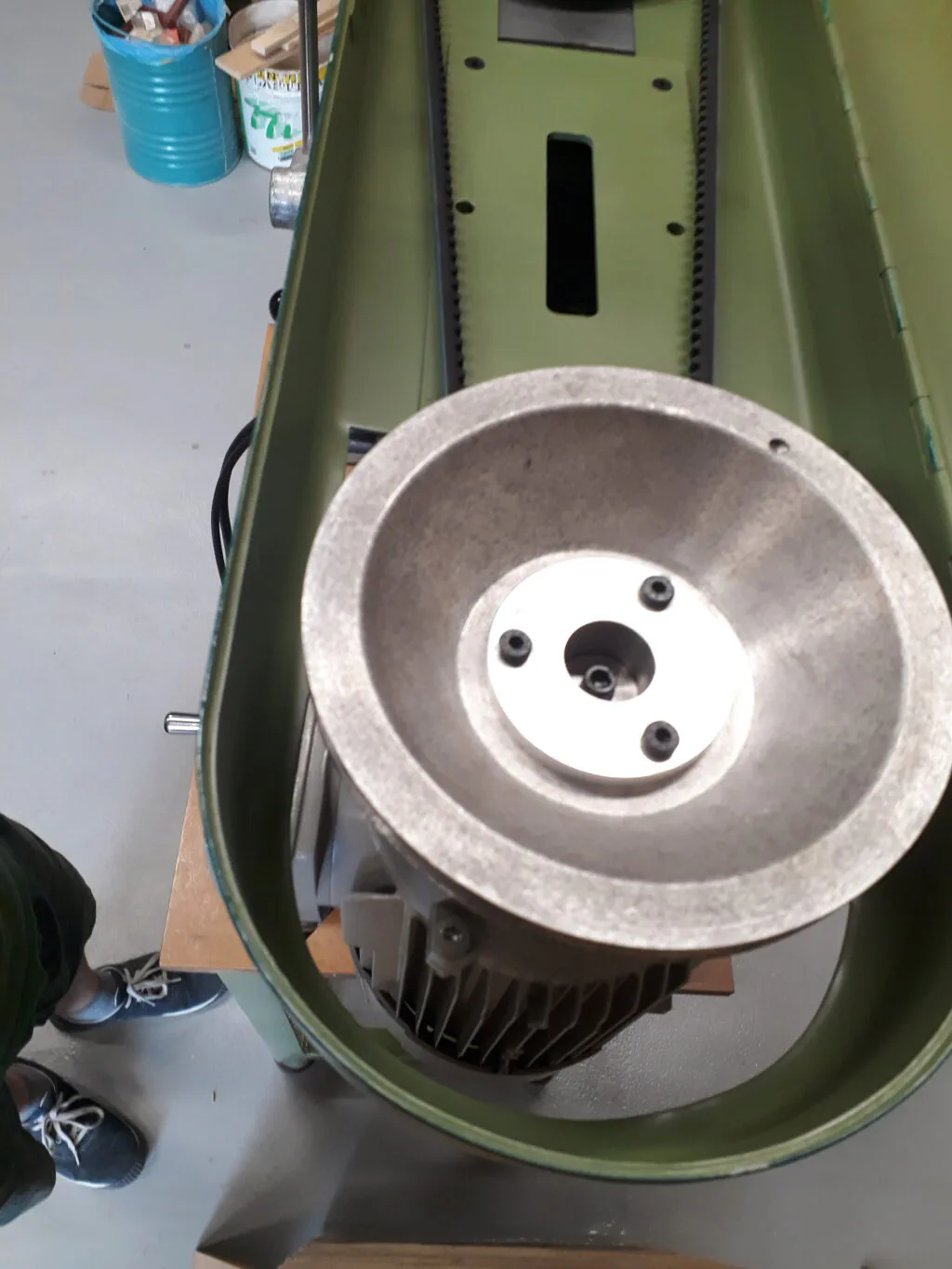
Top view of the pulley system. The drive pulley can be seen mounted to the motor shaft via the new core.
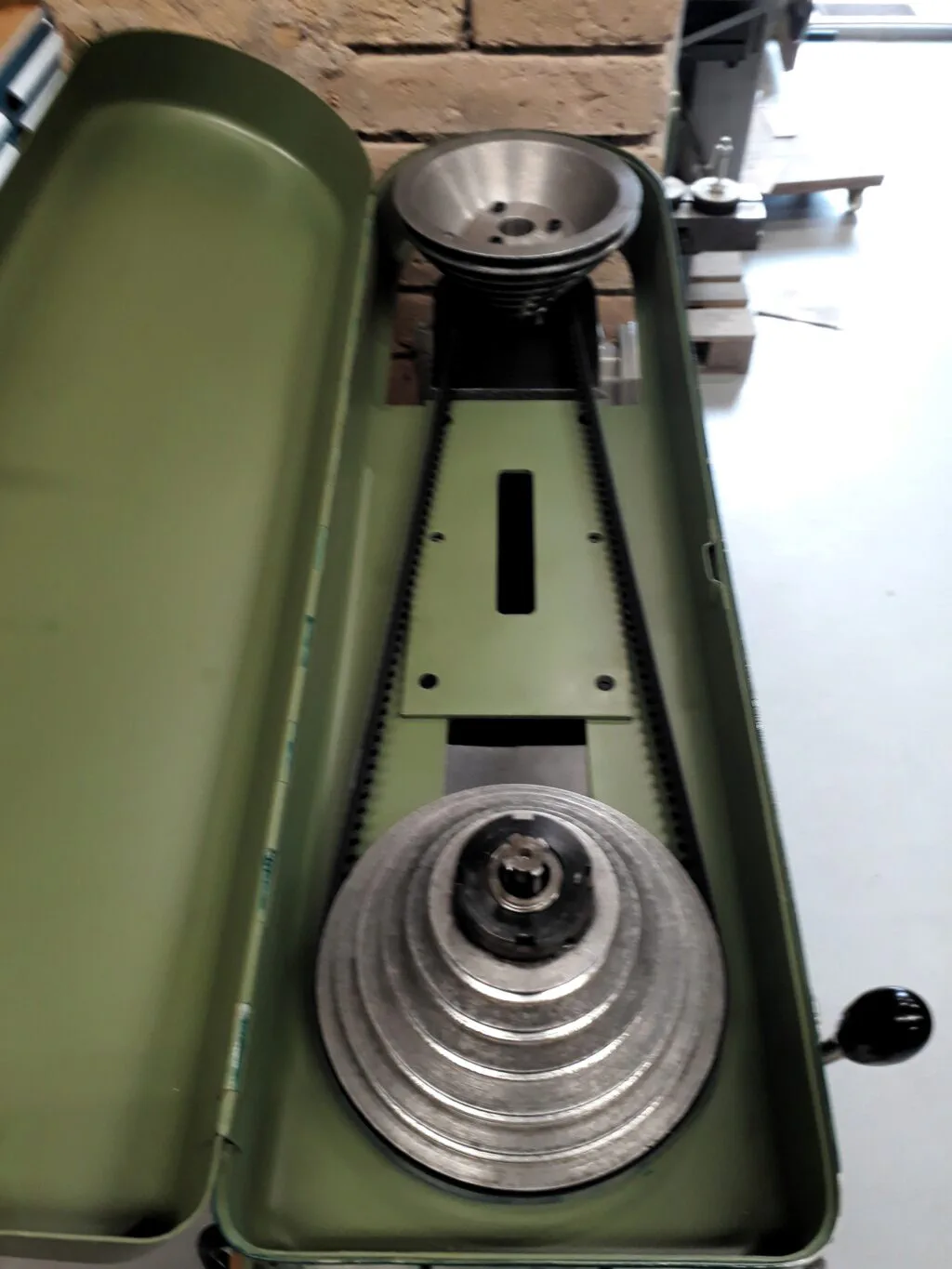
Top view of the drill press pulley system, with the driven pulley in the foreground.