
This entry describes the Cincinnati-Chomienne model FP30 milling machine. It has served me well for a number of years, but it is now up for sale. Literature on this machine is scarce; I have only managed to find manuals for similar Cincinnati-Chomienne models and a brochure that details its main dimensions.
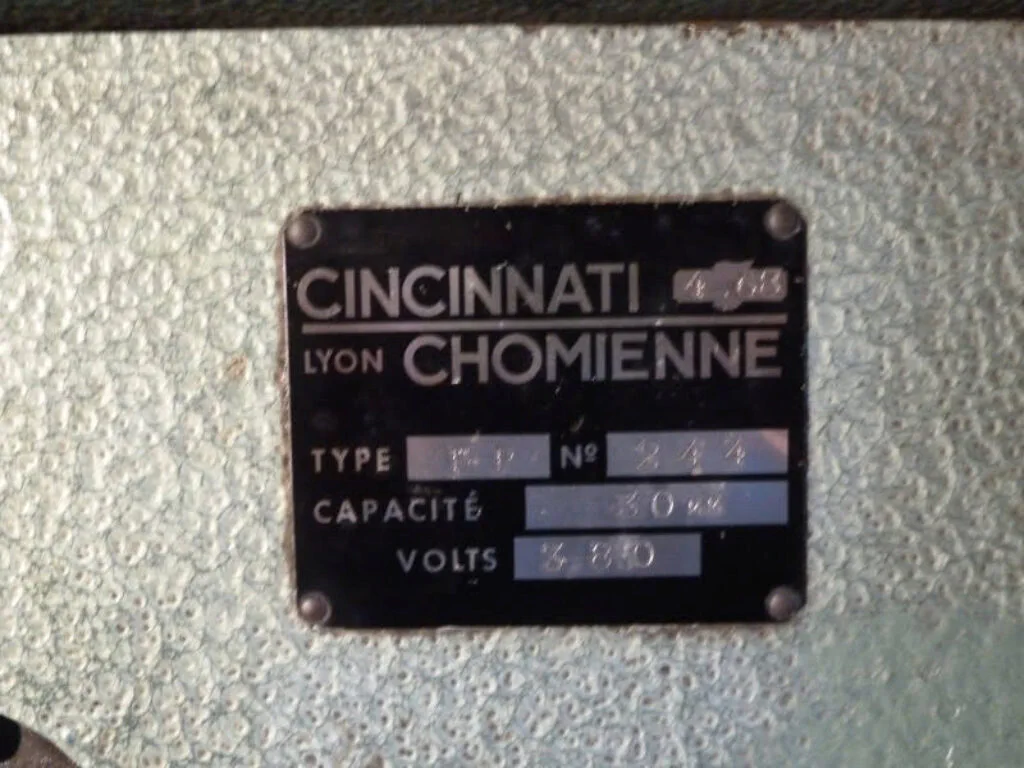
The machine was built in France in the late 1960s (according to the identification plate, in April of 1968). It is a light yet highly capable milling machine that also serves exceptionally well as a drill press. In fact, it can be best described as a vertical drilling and milling machine.
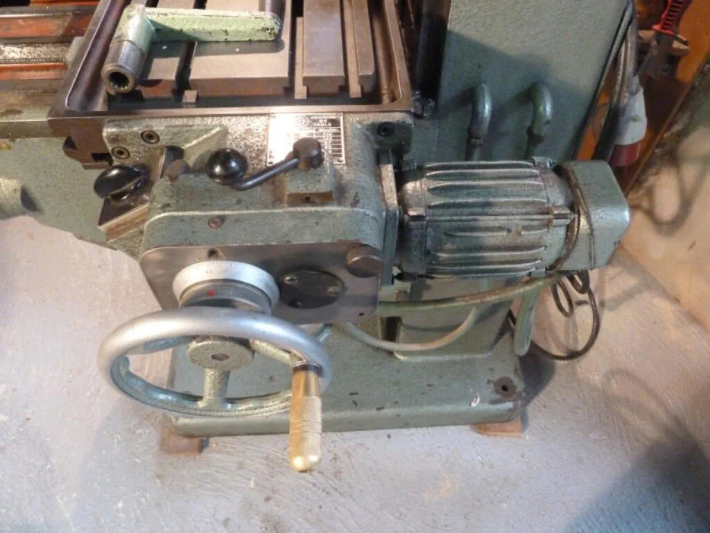
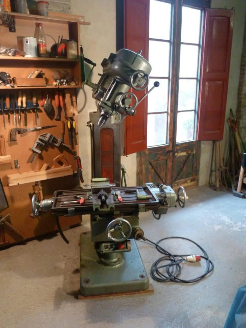
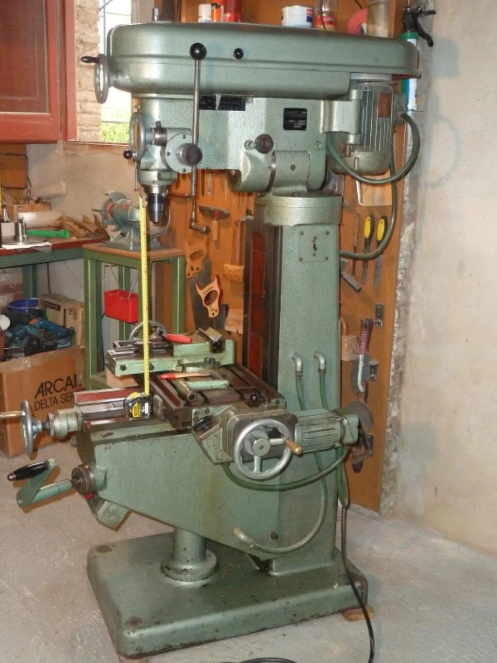
The following pictures show the general layout of the milling machine:
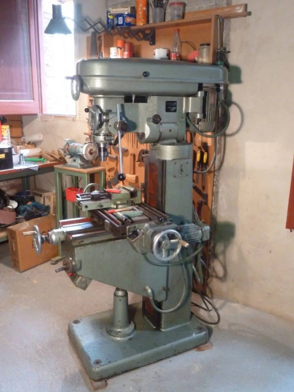
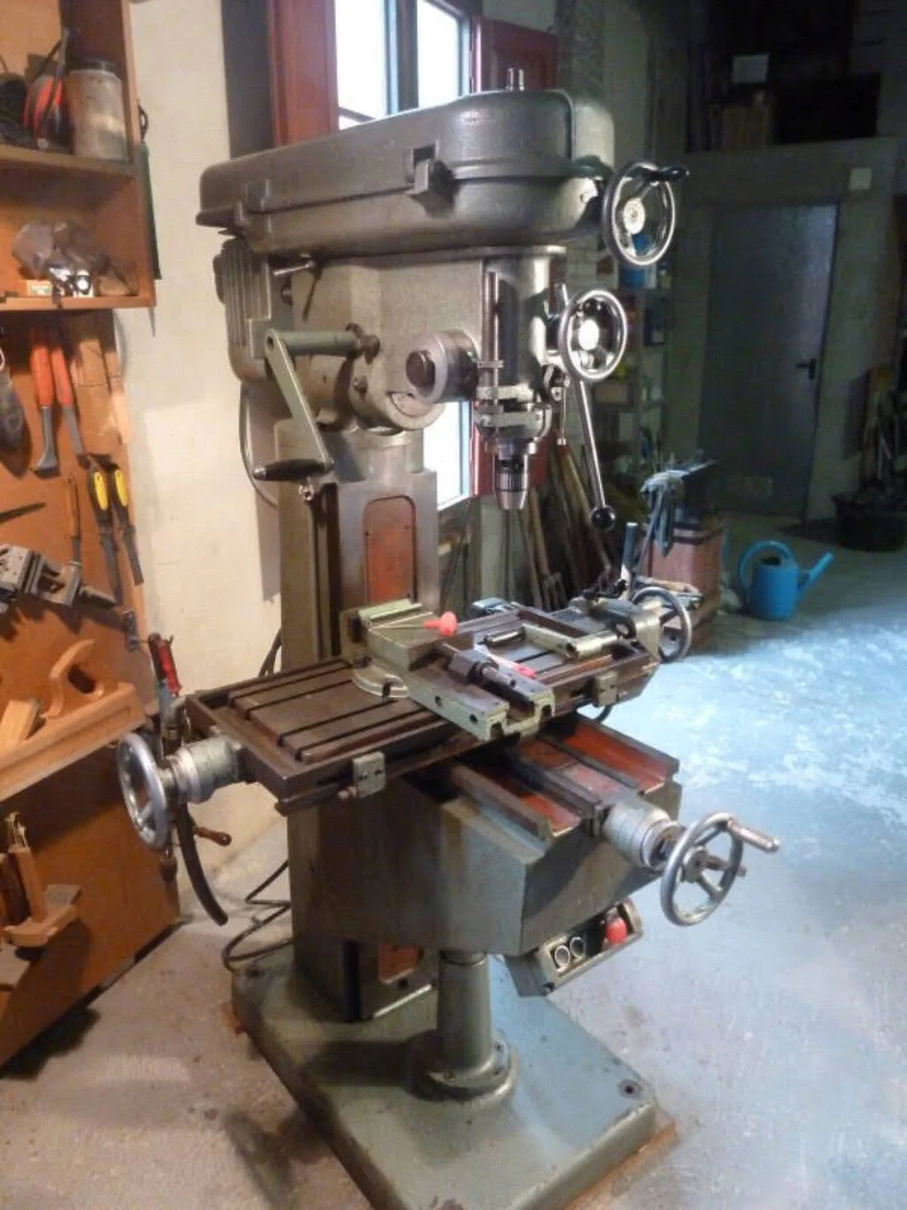
This is its identification plate:
And here are the main dimensions taken from an original brochure:
As you can see, it offers very generous working capacities. The exceptionally long Z-axis travel is especially noteworthy!
Additionally, these are its most prominent specifications:
- Spindle with an ISO 30 taper
- A quill travel of 120 mm
- Spindle speeds ranging from 125 to 5000 rpm
- 1.5 HP main motor
- Belt-driven variator drive for the spindle (no gears involved), which makes it run very silently
- Head can be tilted up to 60 degrees
- The quill can be advanced quickly via a feed handle or slowly via a worm gear, making drilling and reaming straightforward
- All graduated dials read in increments of 0.02 mm, including the fine quill feed
- Power feed unit on the X-axis, with different feed rates achieved by changing a pair of gears
The Spindle Drive Unit
The spindle is directly driven by a belt variator. Because there are no gears involved, the machine runs very quietly, even at high speeds. The variator operates across two speed ranges by changing the belt positions. The intermediate pulley shifts back and forth via a lever on the front of the machine; simultaneously, an indicator moves across a scale to show the approximate spindle rpm.
Below are a couple of pictures showing the spindle drive system:
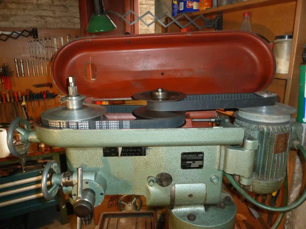
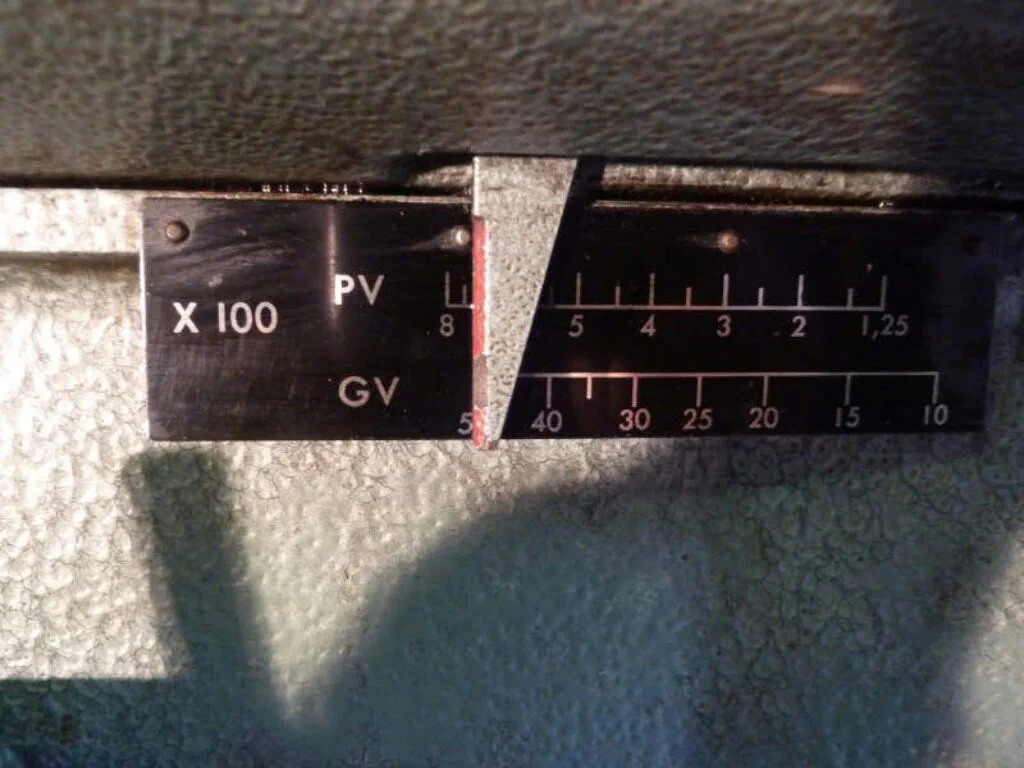
Note that the belts were replaced recently and are brand new. The overall speed range spans from 125 to 5000 rpm.
The Quill Feed Mechanism
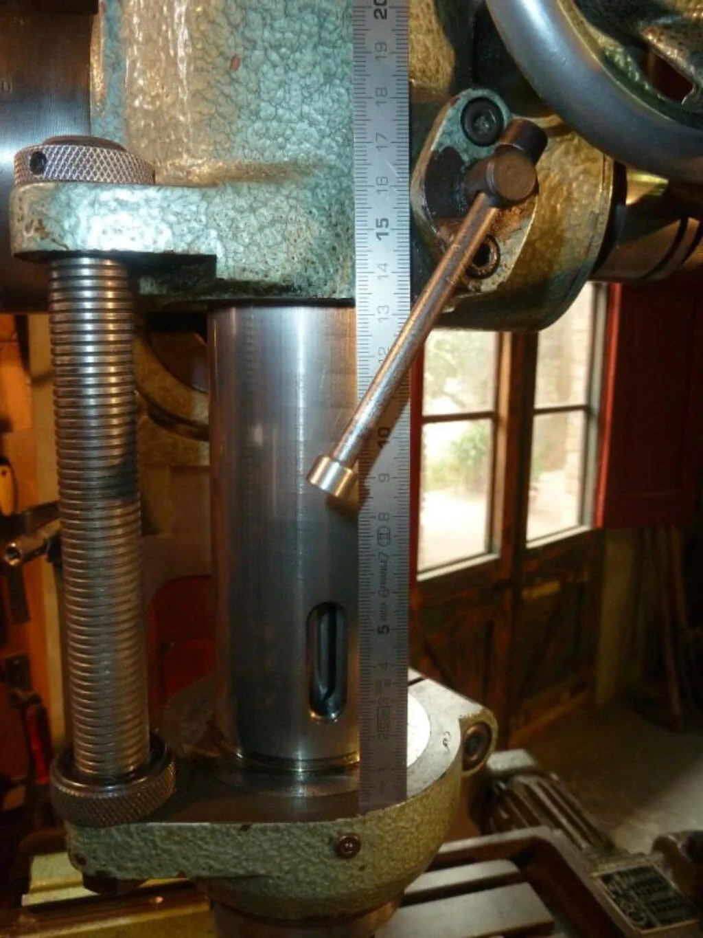
The machine head features a quill mechanism that allows for a vertical travel of about 120 mm. It is worth noting that most milling machines of this size — such as the Sixis 103, Schaublin 13, or Deckel FP1 — have a quill travel of only about 60 mm, if they have one at all. The quill can be locked in any position with a clamping lever, and it includes standard upper and lower depth stops. The picture below shows the quill at maximum extension. Notice that the lower depth stop includes an O-ring to prevent the quill from slamming into the bracket when it retracts under spring tension.
The quill can be operated by two different mechanisms. The first is a standard feed handle that acts directly on a conventional rack-and-pinion assembly. This mechanism allows for a rapid but controlled descent of the spindle, making it ideal for drilling operations.
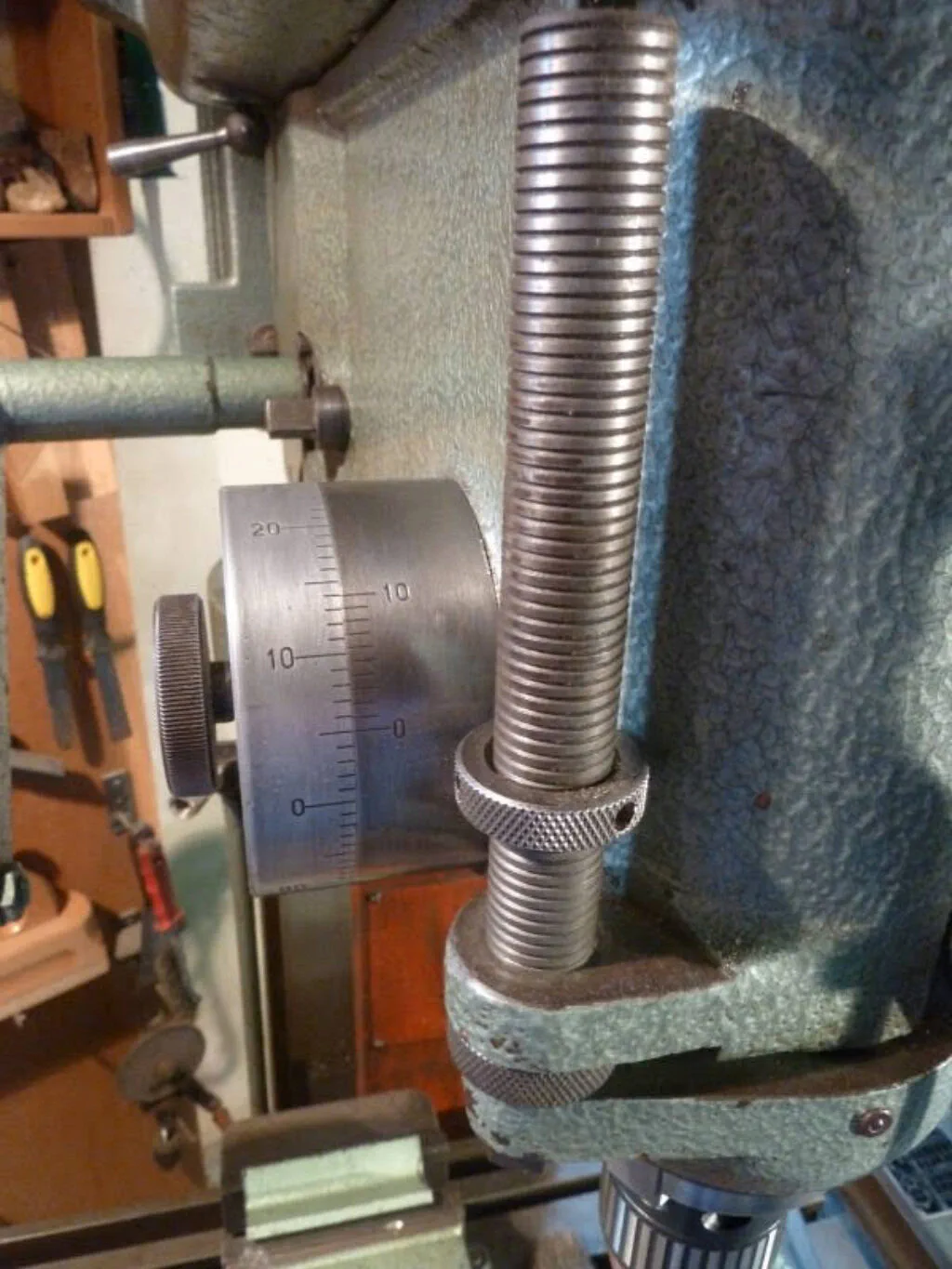
The second mechanism rotates the pinion via a worm drive operated by a handwheel. This provides a much finer feed rate suitable for boring operations. This fine-feed mechanism is engaged by rotating the eccentric mount of the worm gear until it meshes fully without backlash. The handwheel features a graduated dial with 0.02 mm increments. The following picture shows this fine-feed mechanism:
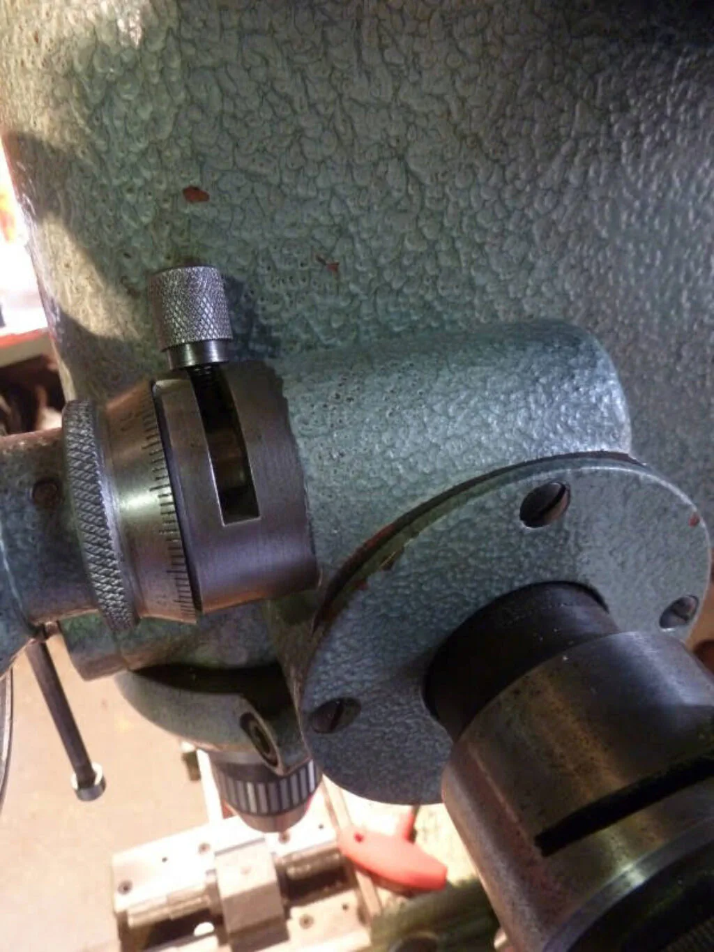
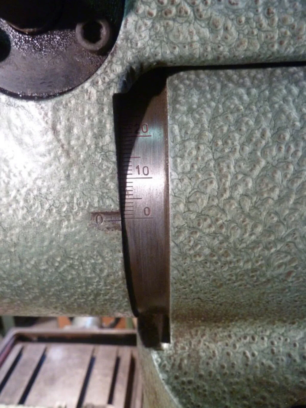
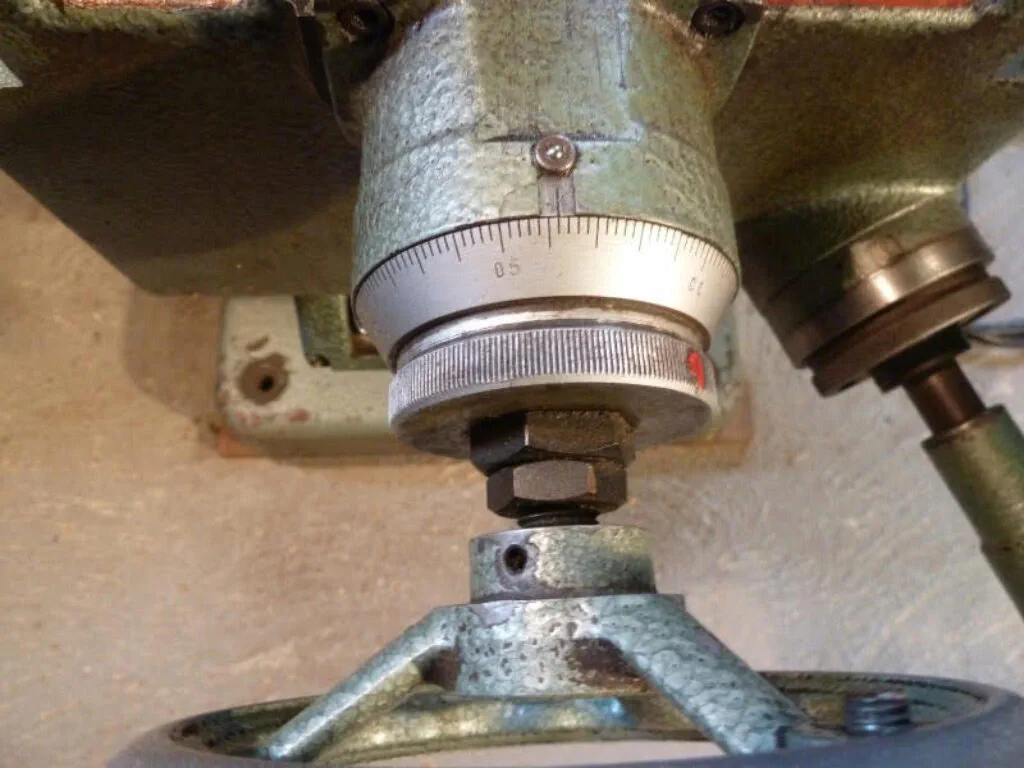
The pinion shaft also houses a clock spring inside a housing to return the quill to its neutral position. The exterior of this housing is graduated and can be read against a Vernier scale to a resolution of 0.1 mm, as seen in the picture below. This is an incredibly useful measuring feature.
The X-Axis Power Feed
The X-axis can be driven by an automatic feed mechanism. It is powered by an independent, small electric motor that can be switched in both directions via a controller next to the table. The feed rate is adjusted by swapping a pair of change gears inside a dedicated gearbox. Because each pair of gears can be reversed, a set of three pairs yields six distinct feed speeds, as detailed on the corresponding chart plate.
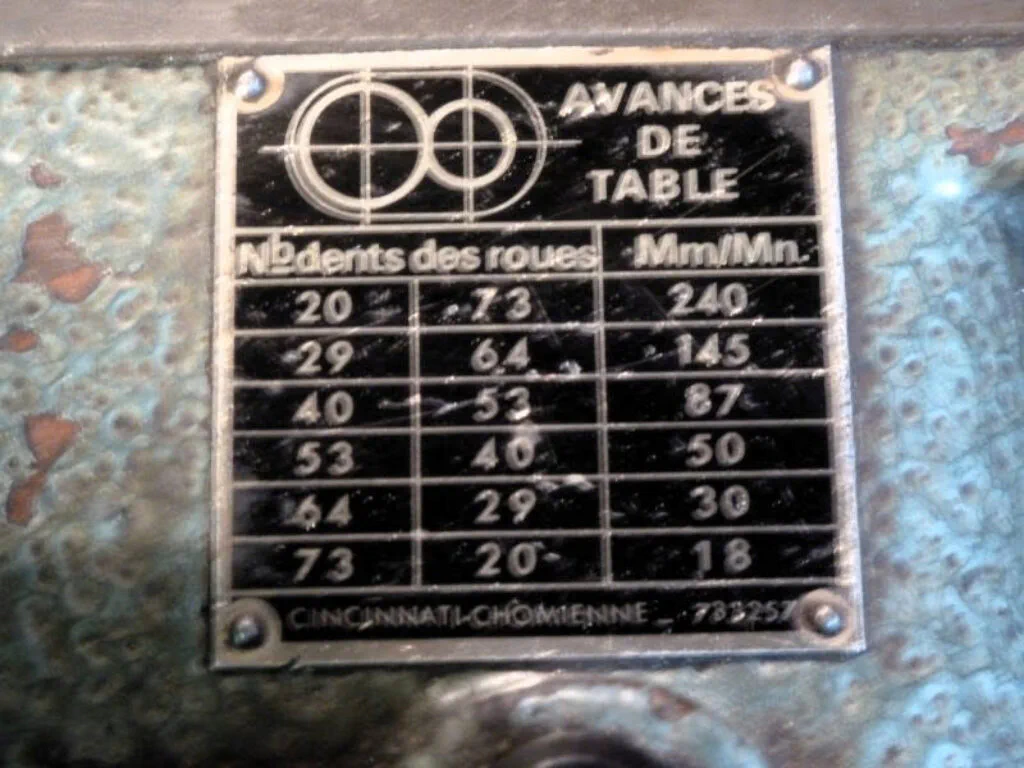
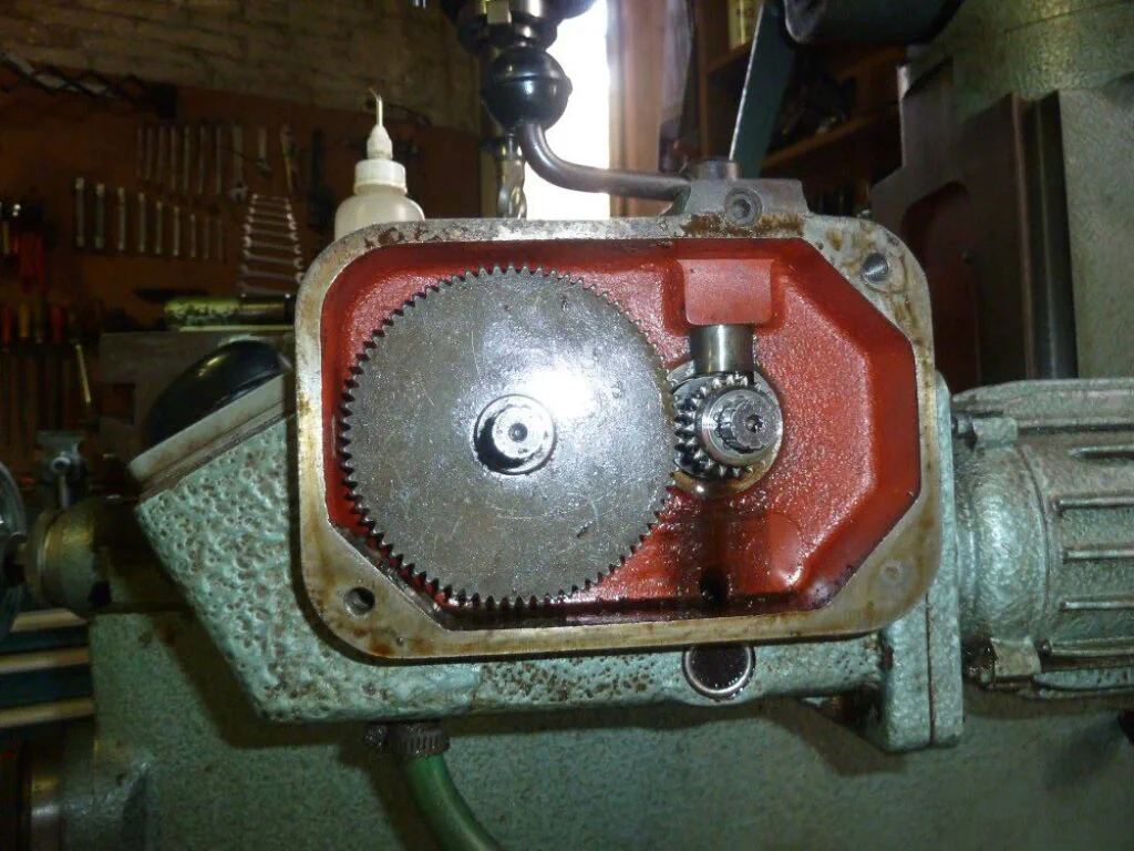
Unfortunately, when I acquired the machine, it came with only two gears: a 73-tooth and a 20-tooth gear. With this single pair, only the maximum and minimum feed rates can be achieved. Below are some pictures of the power feed mechanism, with the last one showing the open gearbox configured for its lowest feed rate.
Tilting the Head
The milling head is designed like a giant hinge, which is visible in the general photos shown earlier. This setup allows the head to pivot around a heavy, perfectly fitted cylinder measuring roughly 120 mm in diameter. The tilt angle can be read on a graduated scale, as shown in the next picture:
Tilting the head manually would be heavy work given its bulk, but the task is made easy by a worm gear that slowly rotates the assembly. This worm drive is adjusted using a square-ended stud on one side of the head. Once the desired angle is reached, the head can be locked securely in place using a pair of clamps tightened via square-ended studs. The picture below shows the head tilted at 30 degrees:
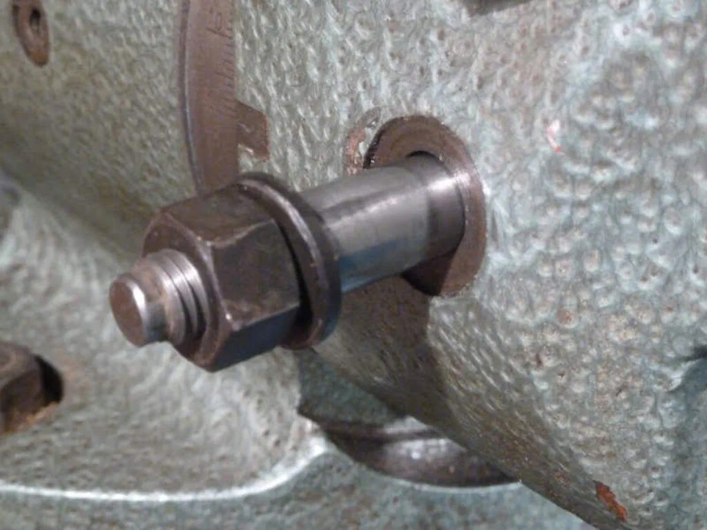
To return the head to the zero position, there is a conical indexing plunger that ensures a perfect vertical alignment when fully seated. Naturally, this plunger must be pulled out before tilting the head; this is accomplished with a clever nut that acts as a built-in extractor. The picture below shows the plunger assembly:
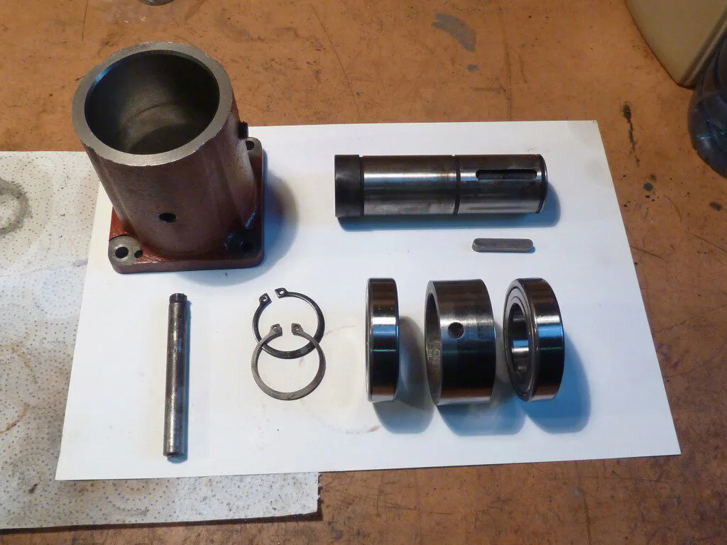
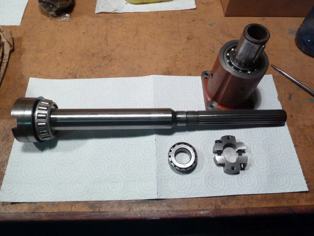
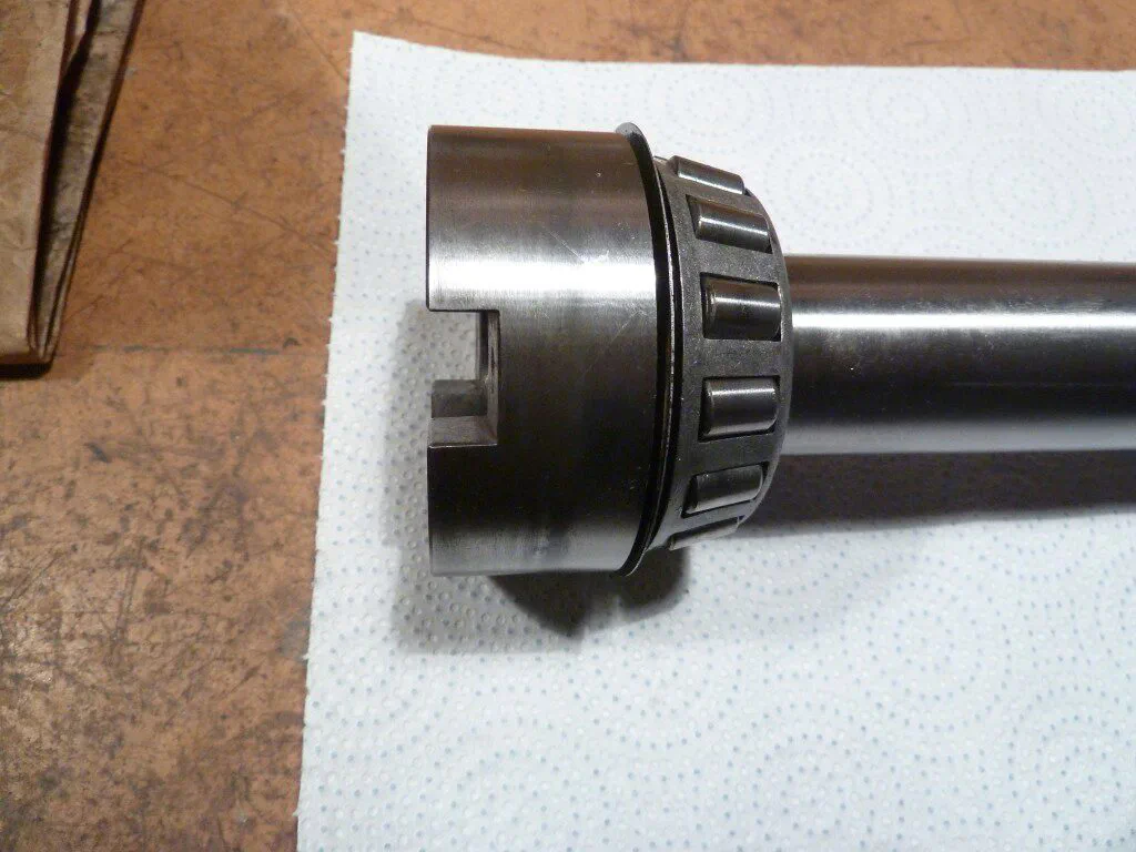
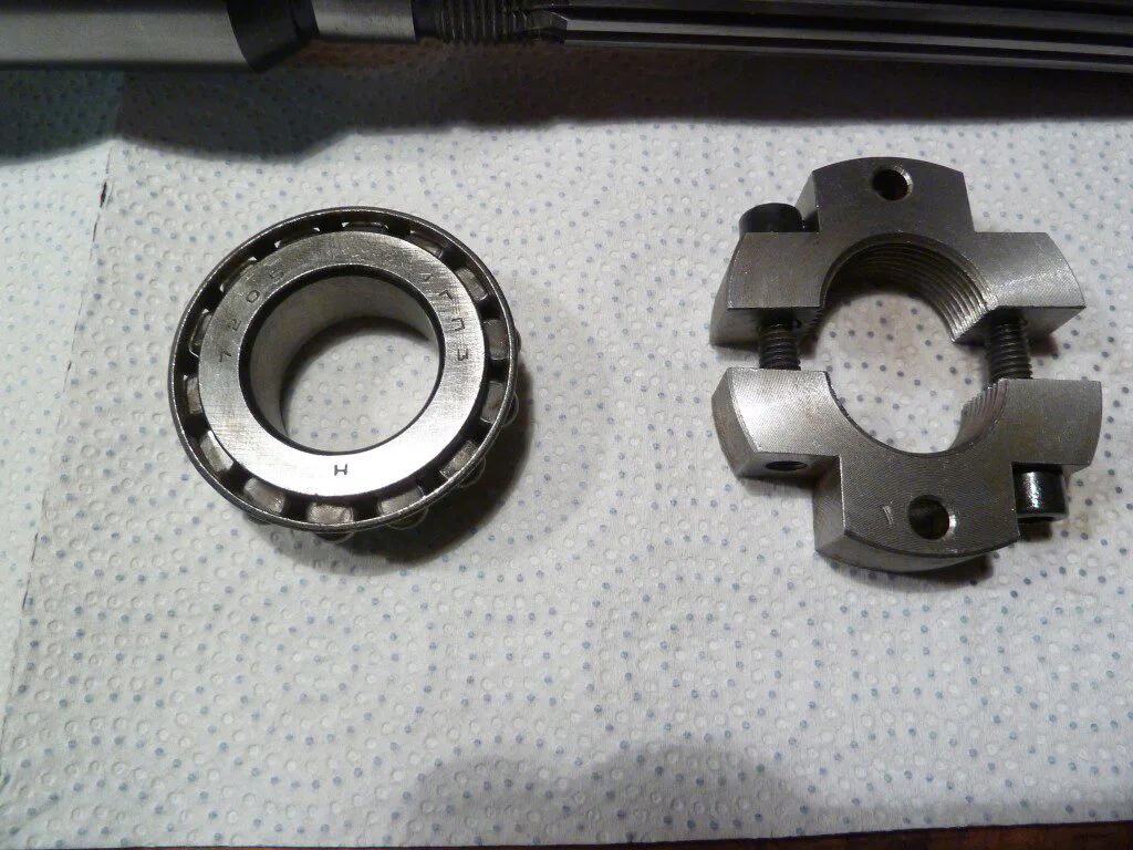
Servicing the Quill and Spindle
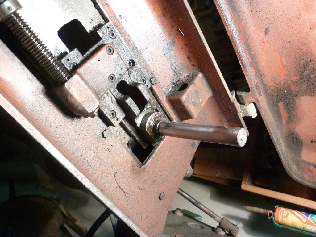
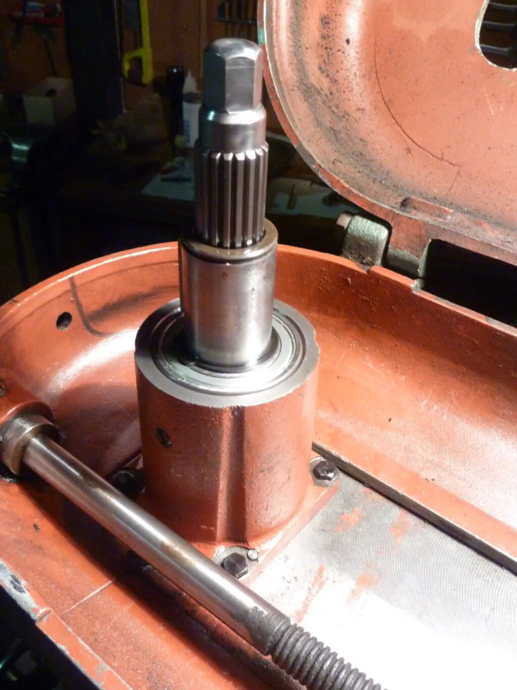
About a year ago, I completely overhauled the quill and spindle assembly: I replaced the bearings supporting the driving pulley, cleaned and relubricated the spindle bearings, and readjusted them. Here are a few photos taken during the process:
Additional Photos
The knee and table at maximum Z-axis travel:
The Y-axis graduated dial, finished in satin chrome:
The Milling Machine Leaves the Garage

Videos of the Machine in Operation
Drilling a piece of scrap metal:
Face milling a piece of scrap metal:
Historical Documentation and Literature
As mentioned earlier, I am not aware of any specific literature for this exact model other than the brochure referenced in the first section. However, there are several manuals available for similar machines built by Cincinnati-Chomienne (later Cincinnati-Milacron) that share many of the same core components and design principles. The most relevant are: