
For many years, I was the proud owner of an AP lathe (AP being the initials of its maker, Antoni Pujantell). This lathe was the very first machine tool I brought home, and after many years of loyal service, I sold it a few days ago.
When it first arrived from a scrap dealer, it was in poor condition: several parts were broken, it was completely rusted, and its geometry was badly worn from years of use. My father and I spent countless hours restoring it. We repaired broken components, fabricated missing parts like the way wipers, and thoroughly cleaned and lacquered the machine.
However, the greatest effort went into scraping and aligning the main bed ways. My father did this meticulously, putting an immense amount of work into the process. Unfortunately, digital photography didn’t exist yet, so I don’t have many records of the restoration, other than this photo of my father working on the lathe a few months after it was brought back to life:
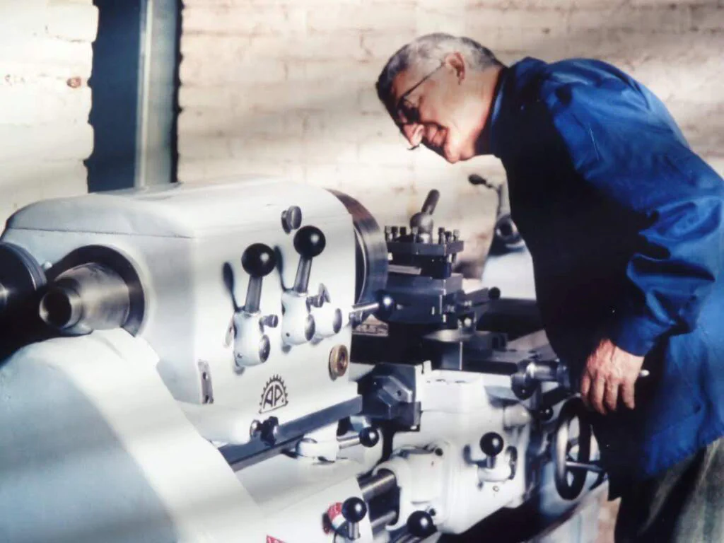
This post is a tribute to all that hard work, a project we enjoyed immensely.
Lathe Specifications
The AP lathe is a heavily built production machine. Its main specifications are:
- 1000 mm distance between centers
- 250 mm swing over the carriage
- 400 mm swing over the bed ways
- 600 mm swing with the gap block removed
- 3 HP motor
- Morse taper 3 (MT3) tailstock
- Imperial threaded spindle nose with a Morse taper 5 (MT5) internal taper
- 40 mm spindle bore (pass-through)
- 300 mm bed width (prismatic V-ways)
- All-geared headstock drive (12 speeds)
- Spindle supported by two adjustable tapered roller bearings
- 8-position Norton quick-change gearbox for Imperial threading
Illustrated Notes
The Headstock and Spindle Drive
The spindle is driven by a gear train enclosed within the headstock. An oil bath provides lubrication for both the gears and the spindle bearings, as shown in the pictures below.
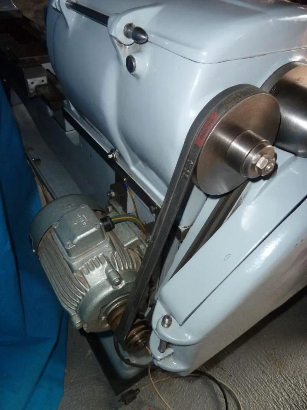
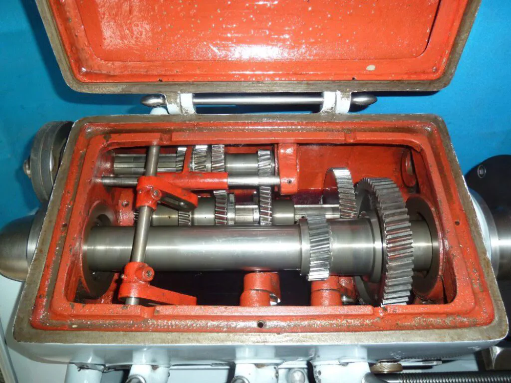
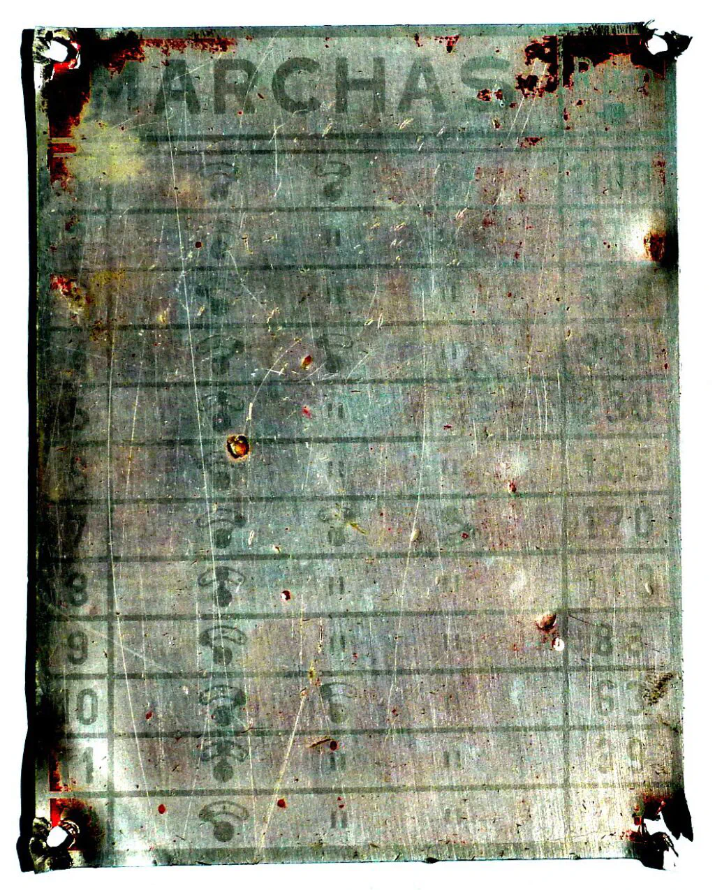
Spindle speeds are selected using a combination of three front-mounted levers, offering a total of 12 speeds ranging from 28 to 1100 rpm. The speed chart plate had to be removed during restoration because it was in poor condition. The best image we have of it after cleaning and treatment is this one:
The Norton Gearbox
The lathe features an Imperial leadscrew driven by a Norton quick-change gearbox, providing the following ratios (the item number corresponds to the lever position):
- 1
- 8/9
- 16/19
- 4/5
- 8/11
- 2/3
- 8/13
- 4/7
In addition, a three-position lever marked A, B, and C acts as a multiplier with the following factors: A = 1/2, B = 1, and C = 2. The standard ratio is achieved with the levers in position 1 and B. Based on this, the original chart plate provides these thread tables:
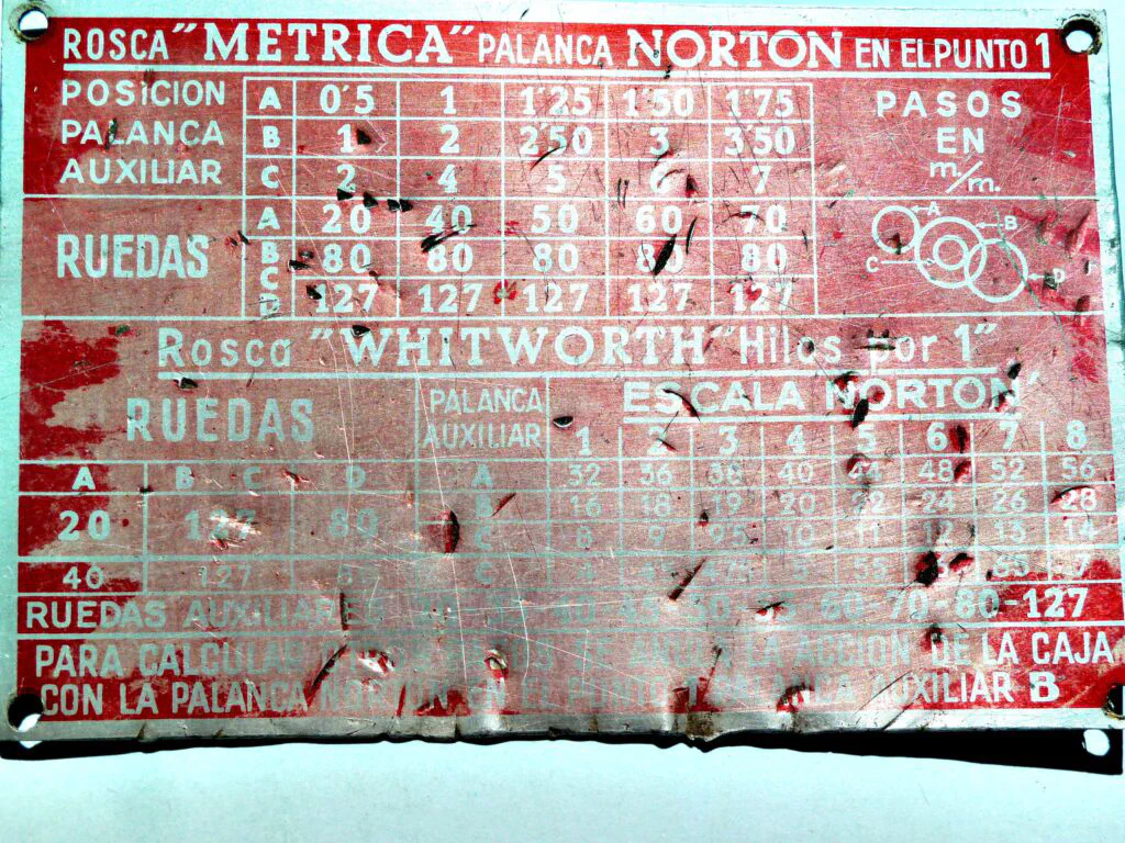
Here are some close-up pictures of the gearbox:
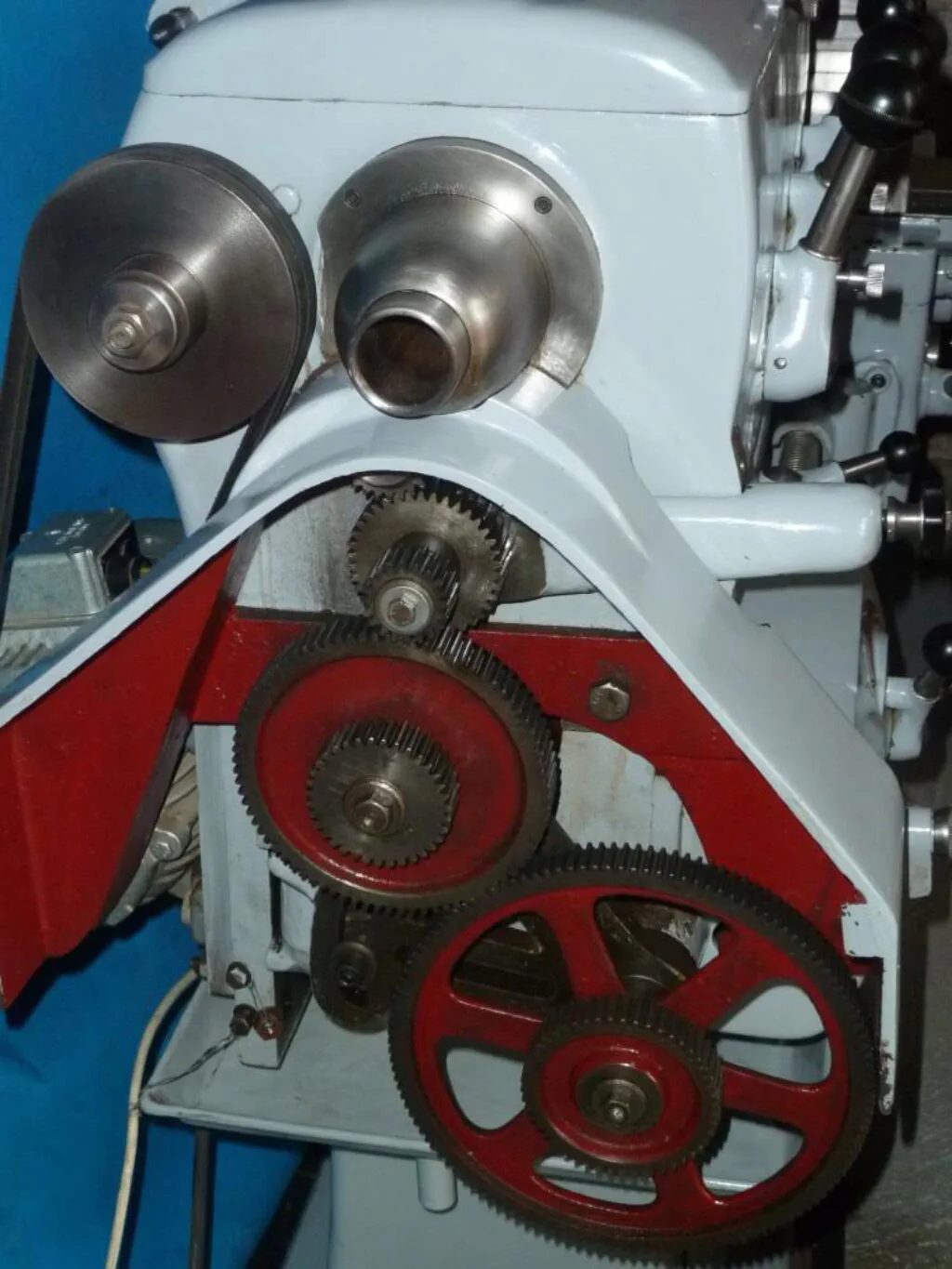
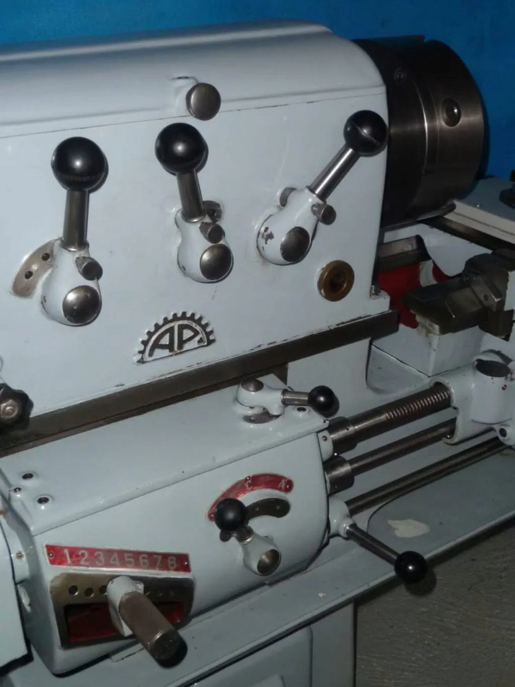
The third lever on top of the gearbox engages and disengages the feed rod and the leadscrew.
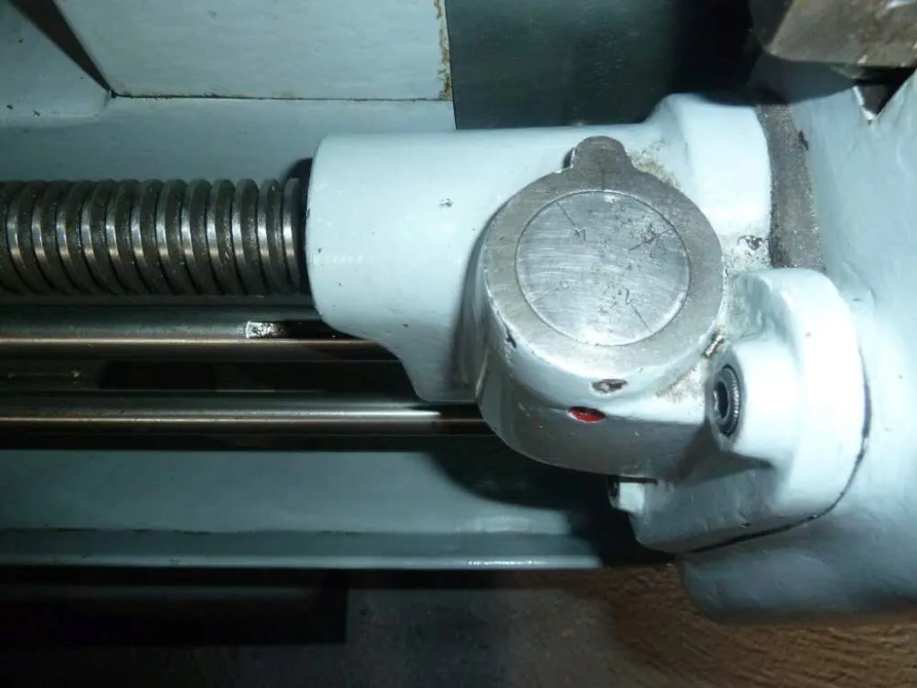
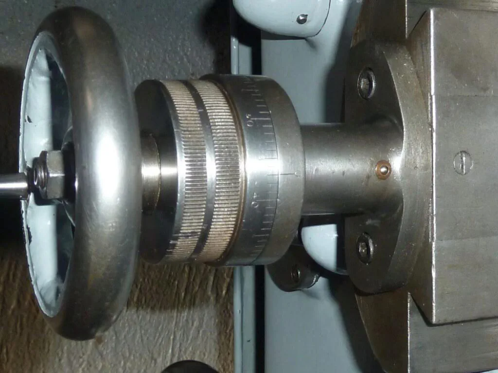
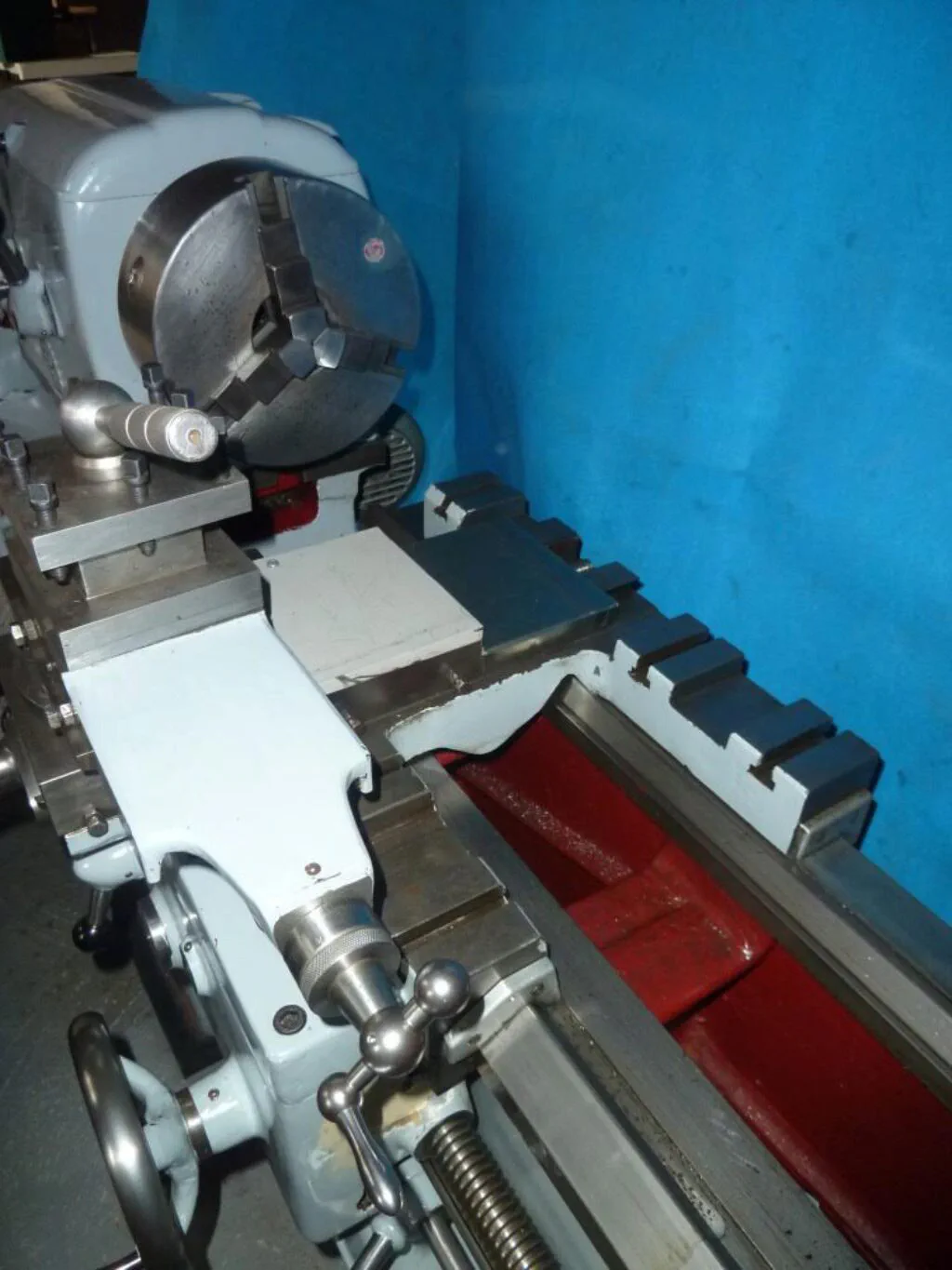
Additional Photos
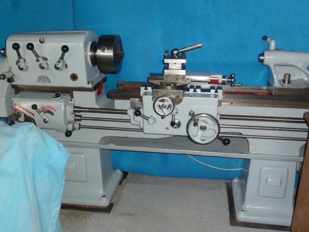
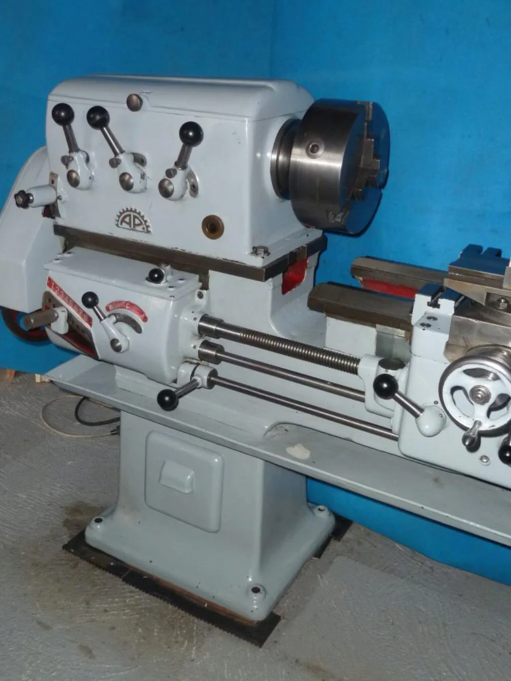
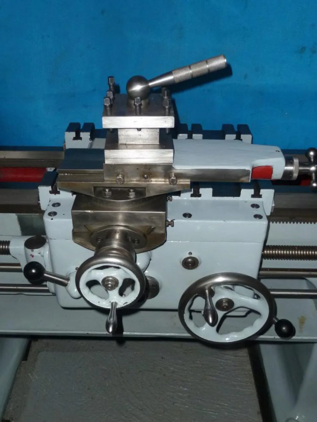
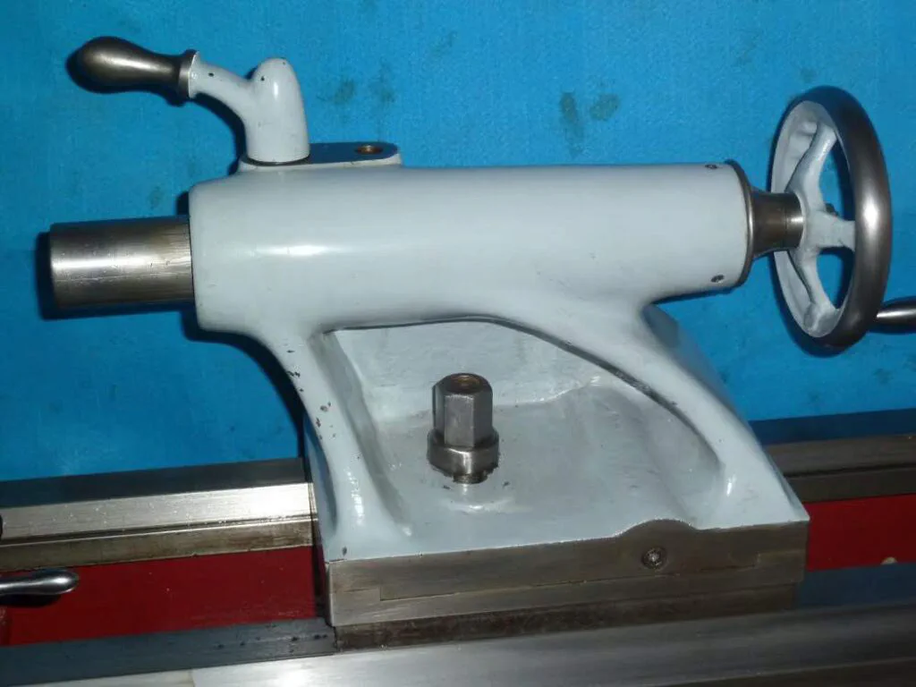
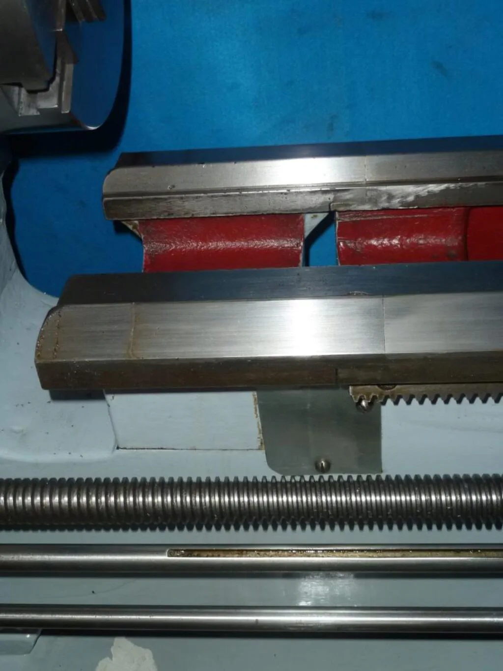
The AP Leaves the Garage
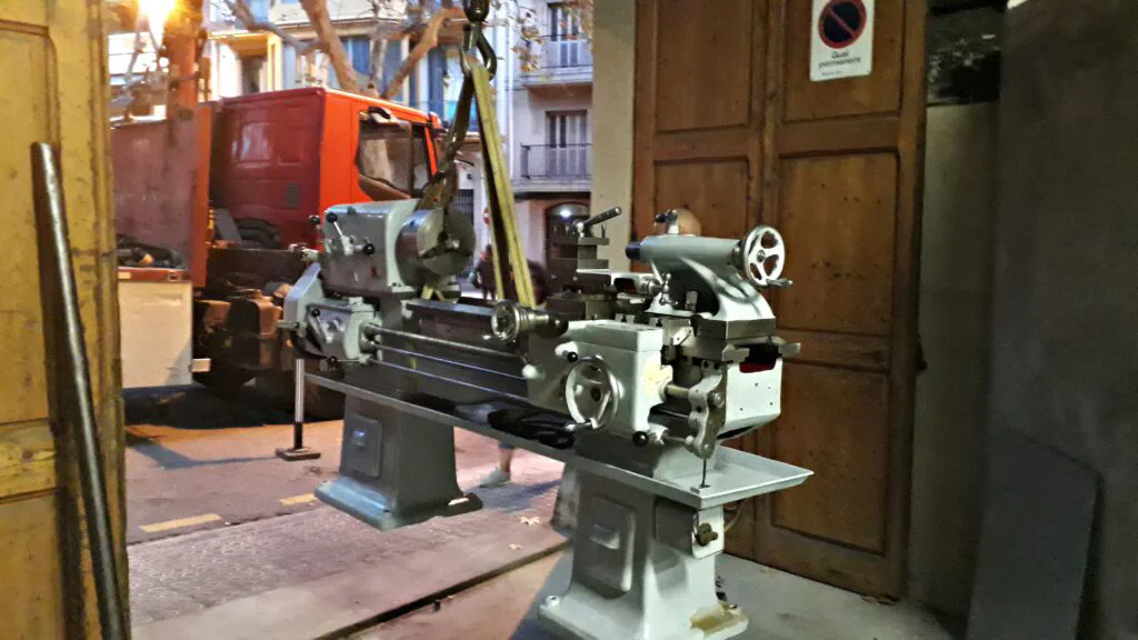
It was a bittersweet moment. The Pujantell lathe finally left the garage after so many years of reliable service. I wish the new owner many hours of successful machining. Here is a picture of the lathe being loaded onto a truck using a hydraulic liftgate.
Historical Documentation and Literature
I am not aware of any printed literature or manuals for this specific lathe, so any information or leads would be highly appreciated. It is worth noting, however, that a brochure exists for a next-generation machine built by the same manufacturer — the AP model E-2 lathe. Judging by its appearance, I believe it dates back to the late 1960s or early 1970s. Consequently, I suspect that the lathe featured in this post was manufactured in the early 1950s. As you can see, the E-2 shares several core components and design characteristics with its predecessor.
According to a helpful reader, AP lathes were manufactured in Lleida, Catalonia. It was a family-owned business that closed down several decades ago. The same source mentioned that the former owners have since transitioned into a farming business.