
The last step in rebuilding the Schaublin 13 has focused in th electrical cabinet and wiring. The machine has been adapted to ordinary 230V monophasic mains by using VFD’s and all the control circuits have been assumed by the same VFD’s.
Just like with other rebuilt machines, I adapted the Schaublin 13 to run on standard single-phase 230V home power. The key to the new wiring is using VFDs, which allow the machine’s three-phase motors to run on single-phase power. Modern VFDs also come with lots of logic functions, making it easy to replace the old relay circuits with the VFD’s built-in logic. I always aim to keep the control interface the same as the original machine, so from the user’s perspective, there’s no difference. This involves using the original switches in a specific way, but it’s usually doable. With the Schaublin 13, it was straightforward to achieve.
Rebuilding steps
During the rebuilding of the machine, I replaced the internal wiring protection conduits and hoses with new ones. Aside from this and painting the cabinet, I followed these steps:
- Dismantled, cleaned, and greased (if needed) all the original switches. The original switches were of high quality, and most were in good condition. The main switch needed some work to fix broken plastic parts.
- Created a detailed wiring plan for the rotary switch. This helped me understand how to use it to manage the VFD’s logic.
- Removed the support plate and dismantled all the relays, contactors, and protection devices that were being discarded. This freed up enough space on the plate to install the new VFDs and other necessary components.
- Mechanically fixed the VFDs and other components in place. In some cases, this required using DIN rails for electrical devices. Most of the devices were attached using reduced head hex screws and the original ones. In some cases, ultra-low head screws were needed. Those are not easy to find, but ARSAM sells them.
- Rewired all the devices according to the new design. Incrementally tested that the wiring was working as expected.
- Installed the plate in the cabinet.
- Connected the machine parts (motors, switches, etc.) to the connection posts on the plate.
- Configured and programmed the new VFDs according to their required functions.
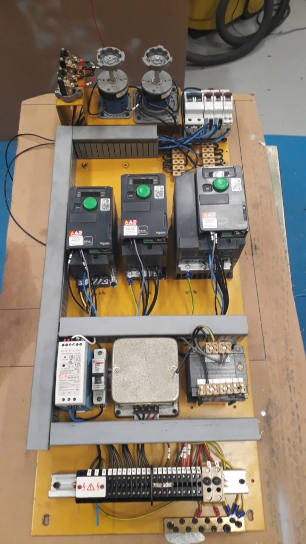 The electrical control plate almost rewired
Some notes
- Chosen VFDs: I opted for the compact Schneider VFDs because their size fits well in the cabinet. The big one for the power motor is the Altivar 320U15M2C. The other two, for the fast feed motor and the coolant pump, are the 320U06M2C and 320U02M2C models.
- Cooling: There’s enough space on top of the VFDs for adequate cooling. Cooling is assumed to be managed through cabinet transmission without any special cooling device. If this proves insufficient, I’ll install a cooling device in the cabinet.
- Control Circuit: Since three VFDs are being controlled by a single circuit, Schneider recommends adding an independent power source unit for the control circuit.
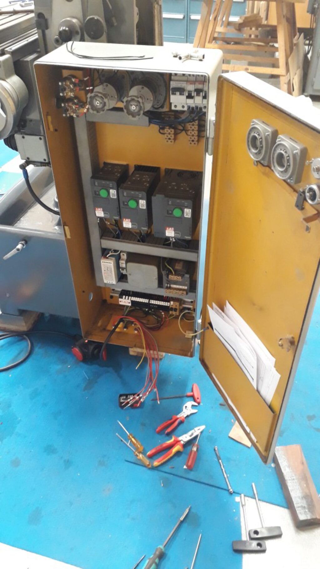 Finishing the connection of the motors in the cabinet
Wiring scheme
I also attach the full scheme of the rewired Schaublin 13, including the main parameters used to configure the VFD’s. It is a set of pdf sheets that include also the references to the devices used.