
Next step in the SV13 overhauling path has been to end the horizontal spindle head and mount it into its ways definitively. Some works remain to be done: finish the fitting of the slideways, clean and relube the feed screw assembly, do the cosmetic work and finally inspect and relube if needed the spindle bearings.
Precisely fit the slideways
In a previous post I explained the firsts steps to refurbish the horizontal spindle head of the milling machine. Its slideways where surely the most weared part of the machine and thus they needed a careful attention. If they where difficult to repair by scraping, the machine refurbish plan would have been reconsidered. Fortunately, as shown in the post, geometry have been improved and the head was then in an acceptable condition. Now it is time to go one step ahead and finish the slideways precisely.
To dimish the rocking motion of the head I decide to apply the same scraping technique I observed on the flat bearing part: the central part was slightly depressed in such a way that contact occurs only on the front and back extremes of the steady slidingway member. Thus I considered the dovetail flat in thirdhs ans scraped slighly deeper the central third. This is applied to the gib and its symmetrical face. With this technique the rocking motion was diminished as needed. At the same time, the aligments where constantly checked to guarantee that othogonality with the table is achieved.
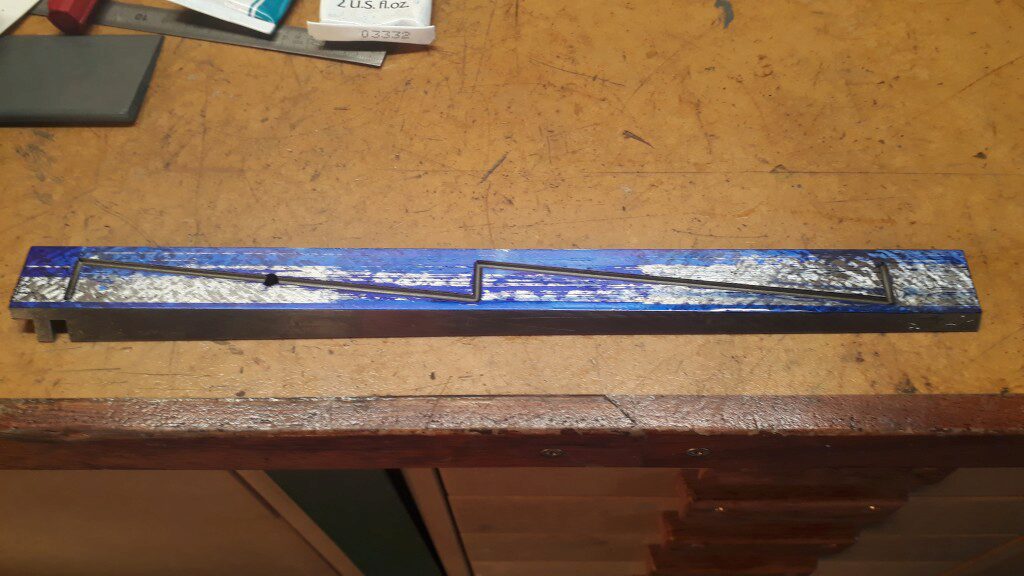
The next picture shows the gib contact during one iteration of the scraping procedure (the contact is not yet perfect). It’s clear that the center is slightly depressed.
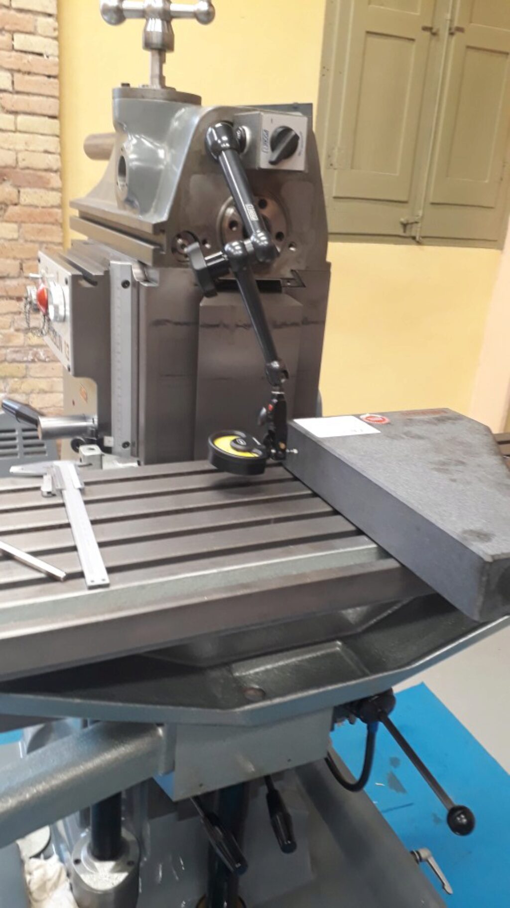
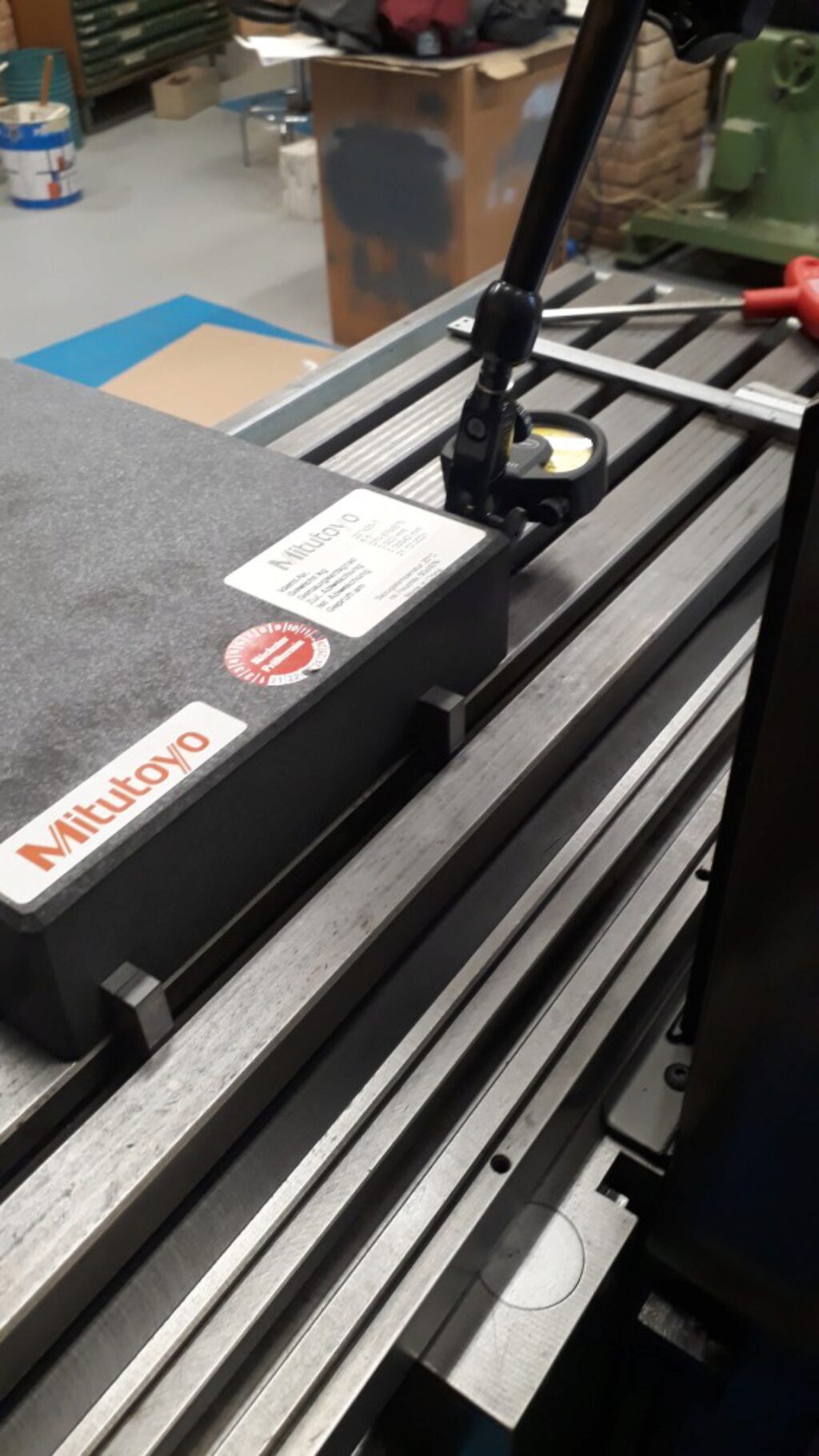
Following, there are two pictures of the orthogonality measuring technique. In this case, a master square against the table slots sets the reference.
Finally a very good fitting and geometry is achieved: no more than 2µm of deviation can be measured as shown in the next video:
The feed screw
The feed screw of the horizontal head is rather complex: it is drived from a top handle or, alternatively, from a side handle. This means that there is some (precise) gearing to adapt the driving handle direction. I dimantled, cleaned and relubed all the bearings and gears belonguin to this set. Bearings where cleaned first in gasoline and then dived into a mix of gasoline and Kluber Isoflex LDS 18 special grease as told by Schaublin manual. After waiting some hours for gasoline to evaporate, the bearing gets perfectly lubed. Gears where greased with Kluber Altemp Q NB 50, a kind of very adherent paste grease as said too in the maintenance instructions.
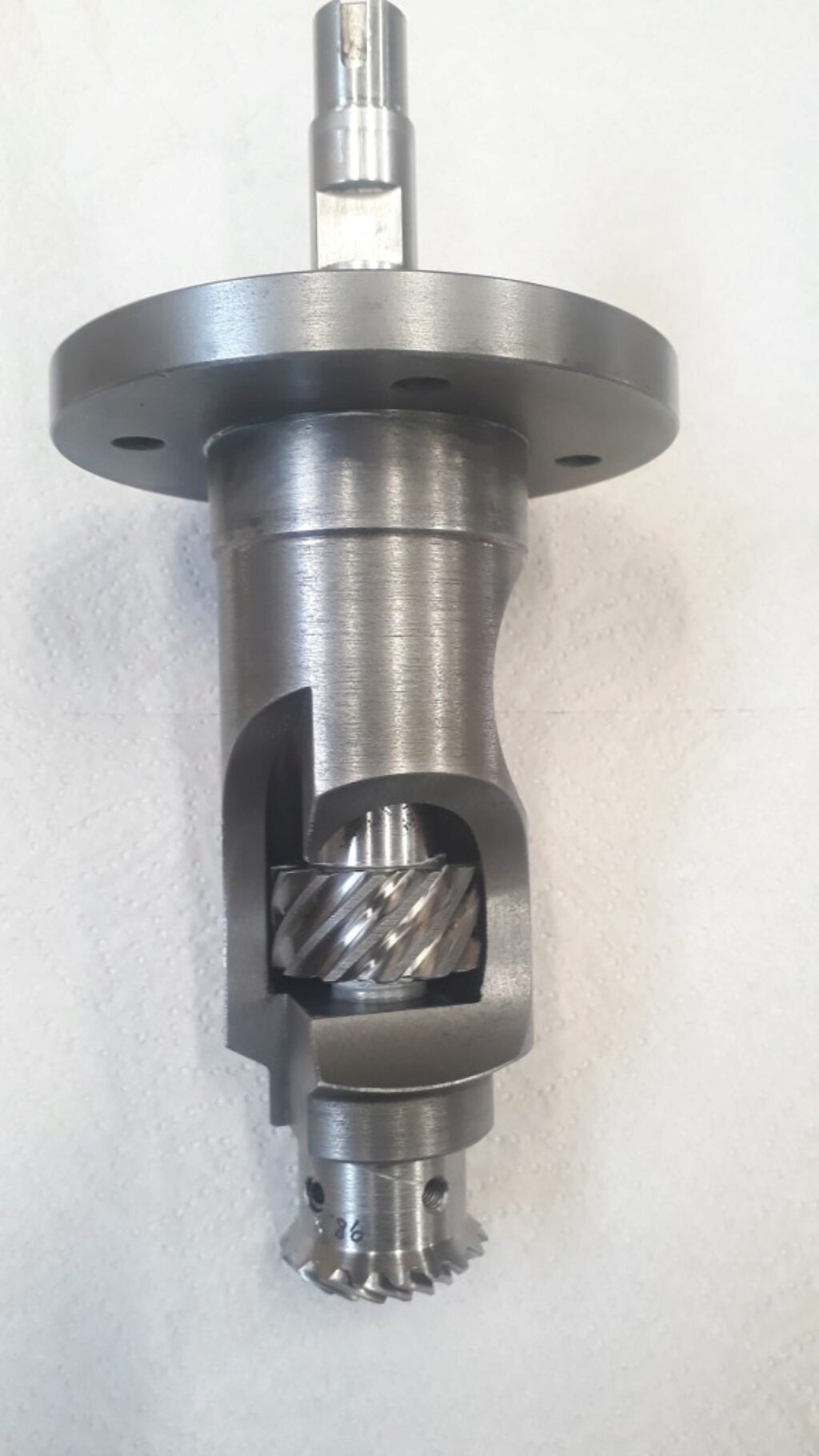
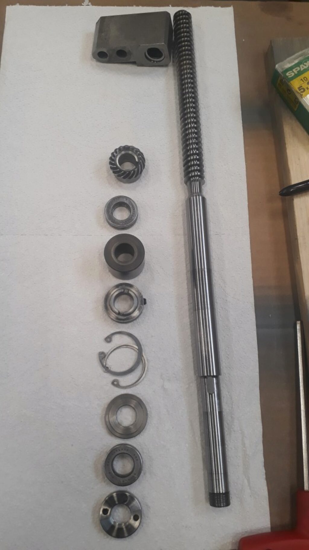
Following, there are some pictures of this assembly. First the subassembly that supports the top handle. It ends with a spiral miter gear that drives the feed screw. In the middle of the shaft, a small screw gear is drived by (or drives) the side handle shaft.
What follows is the horizontal shaft that is rotated by the side handle. It protrudes on each side of the horizontal head.
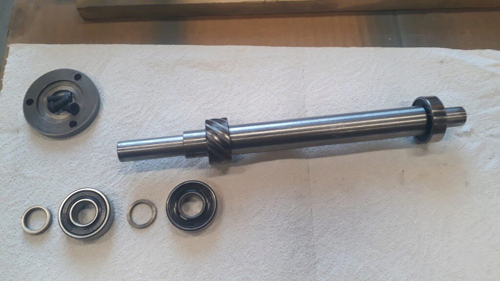
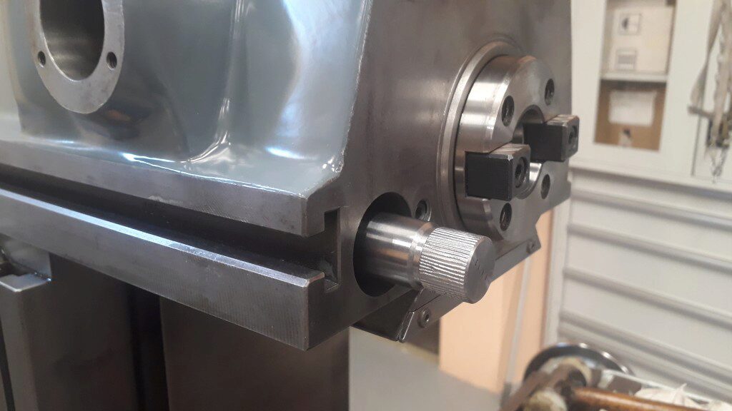
All the above gears are used to rotate the feed screw. This screw assembly is shown in the next picture:
From this, it is interesting to observe this ring:
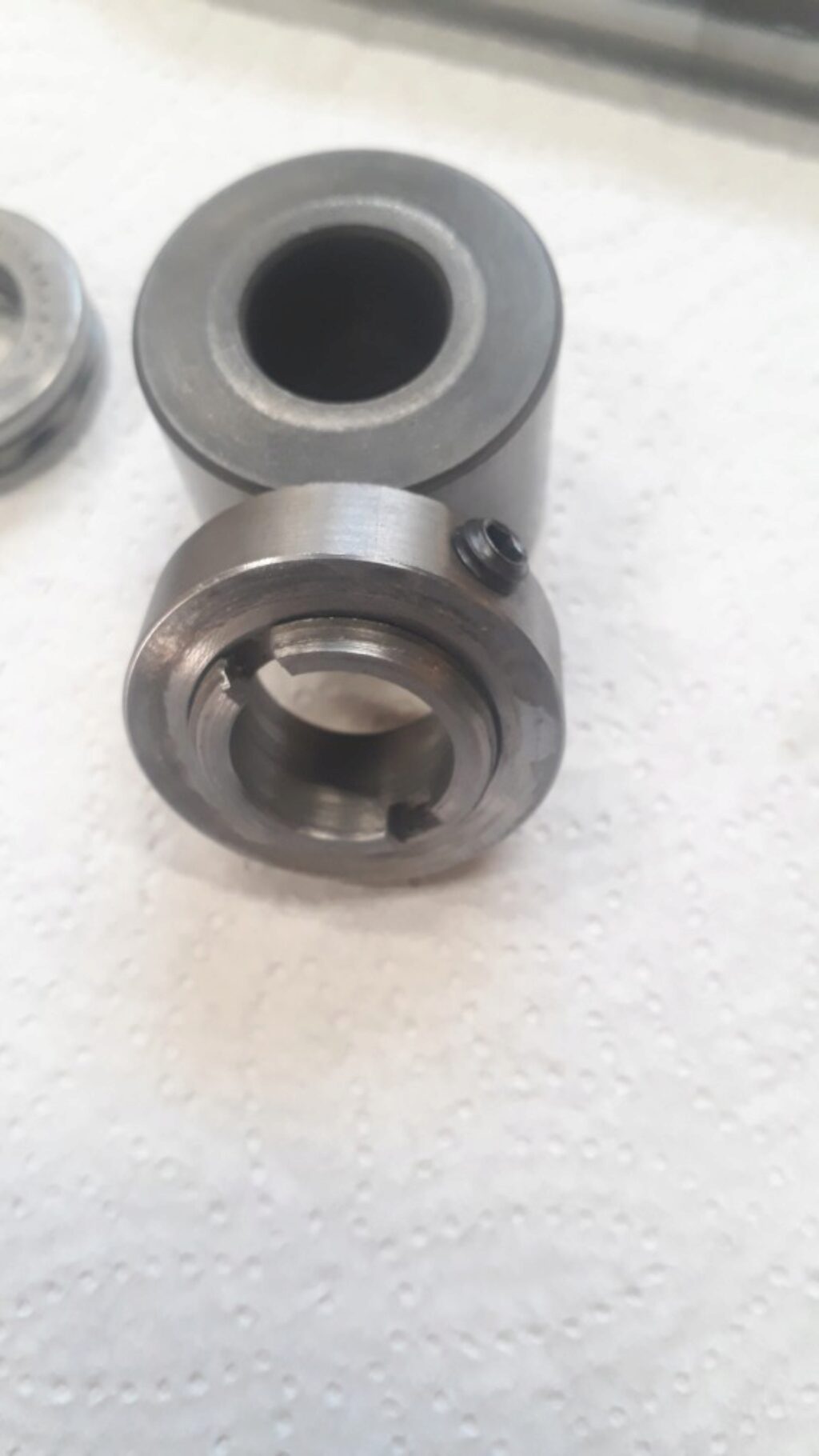
By turning the slotted screw, the length of this separator ring increases or decreases. This allows to slightly move the feed screw bevel gear to adjust the contact with its mating. The set screw of this ring is turned from the bottom side of the head slideway. The adjusting procedure should be done with all the gearing assembled. A special key should be made to ajust the ring:
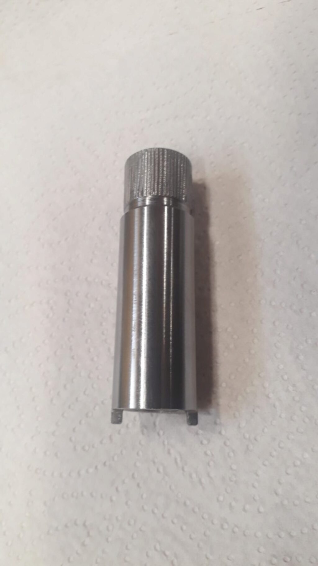
With this mechanism, the play of the gears can be adjusted nicely.
How is the feed screw lubed?
It remains an interesting point to understand. The SV13 manual do not tells about the head feed screw lube. The rest of the machie feed screws are lubed by the pump circuit. This is not the case for this screw. If manual lube where needed, I guess the manual would say it. How can oil end on this screw?
Cosmetic works
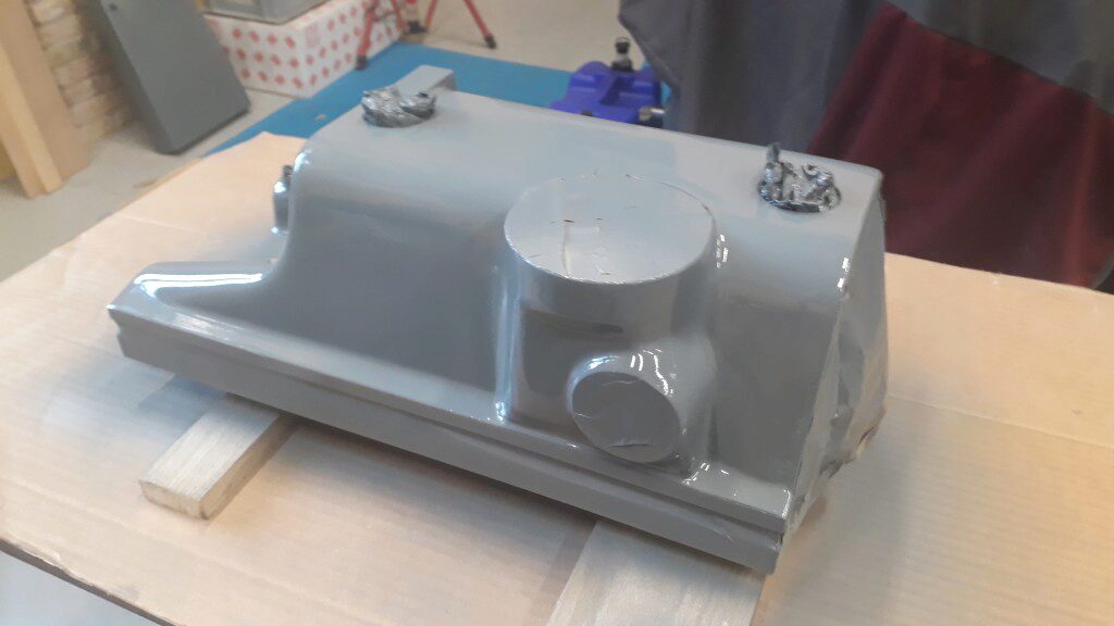
As usual, the horizontal head is beautyfied by smoothing its surface and later on spraying the lacker. Next picture shows the head just after spraying the color coat.
Spindle bearings maintenance
Last step has been to do the spindle bearings maintenance. I hesitate on how to proceed. The spindle was running realy smooth and with a rnout of 2µm. In one hand, the good sense said that better not unassemble it. On the other, take care of it would assure it is well lubed form many time. Finally opted by a intermediate path. I partially extracted the spindle from the head until bearings were visible. Following the manual procedure it was a simple matter. From the sight inspection, I guessed that bearings were relubed a long time ago or maybe never. I prepared a mix of grease and gasoline, injected the mix on the bearings and waited the gasoline to evaporate. Surely not the best but I’m pretty sure a bearings received enough grease for a long time.
I wander if it would have been better to practice a full dissassemble and a new relube. However, this is easy to do in the future if needed.
After assembling again the spindle, the bearings should be preloaded. The manual suggests a 10µm preloading and tells how to achieve by screwing a given angle the adjusting nut of the spindle. I followed this procedure. First, the nut was screwed until no lateral play can be measured. I assumed this is the «0 preload point». After that, the screw is turned by a small controlled fraction as told by the manual. This resulted on a no play spindle and an internal runout of less than 2µm. The next video shows the test: