This post explains the disassembly of the milling machine knee together with the mechanisms related to the automatic traverse feeds. This includes the assembly that drives the traverses from the main motor.
Take apart the table slide
The first job is to take down the table slide. This isn’t very difficult: loosen the spindle nut; put apart the right spindle handle box; finally pull the complete spindle and nut from the left.
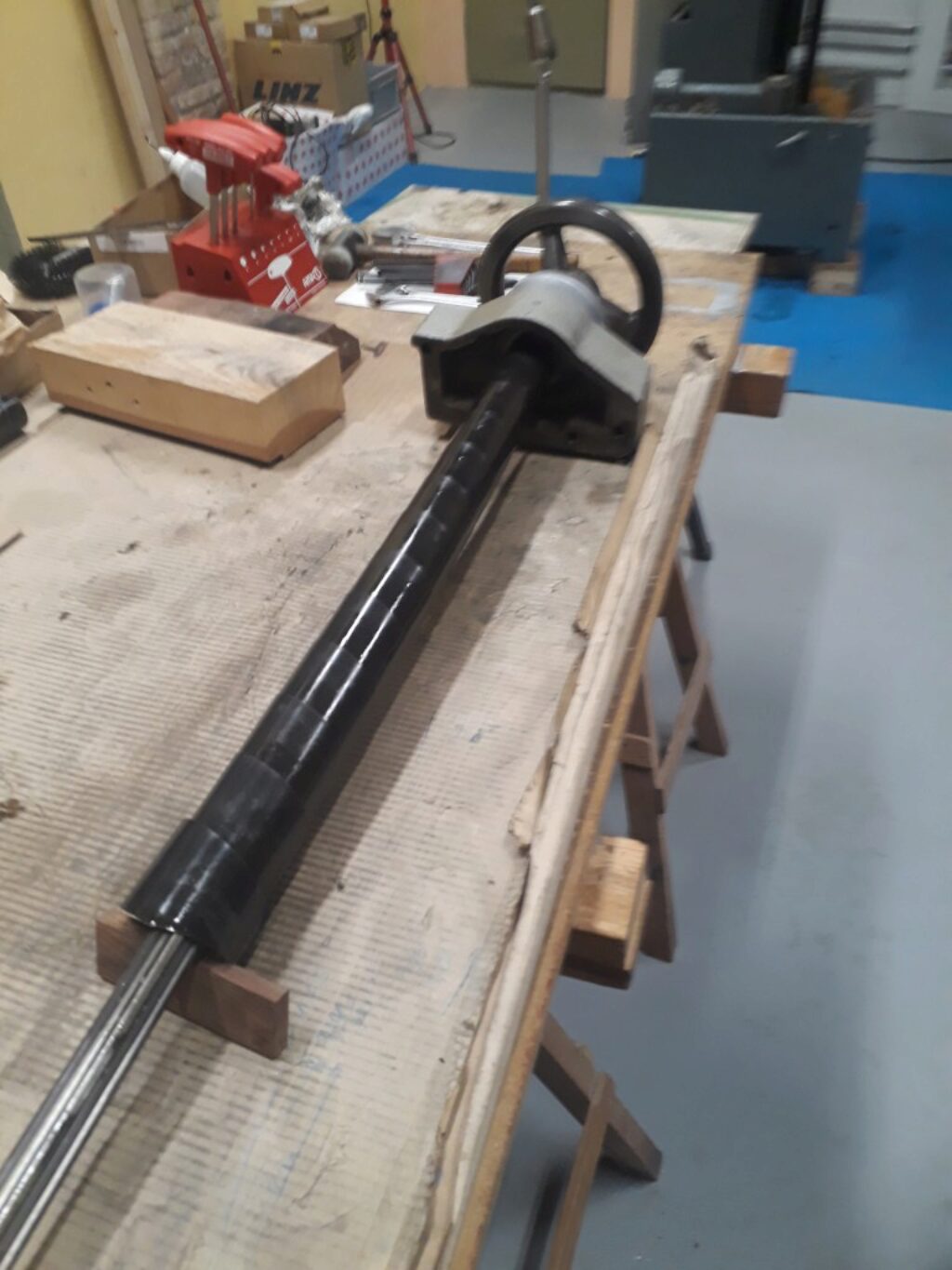
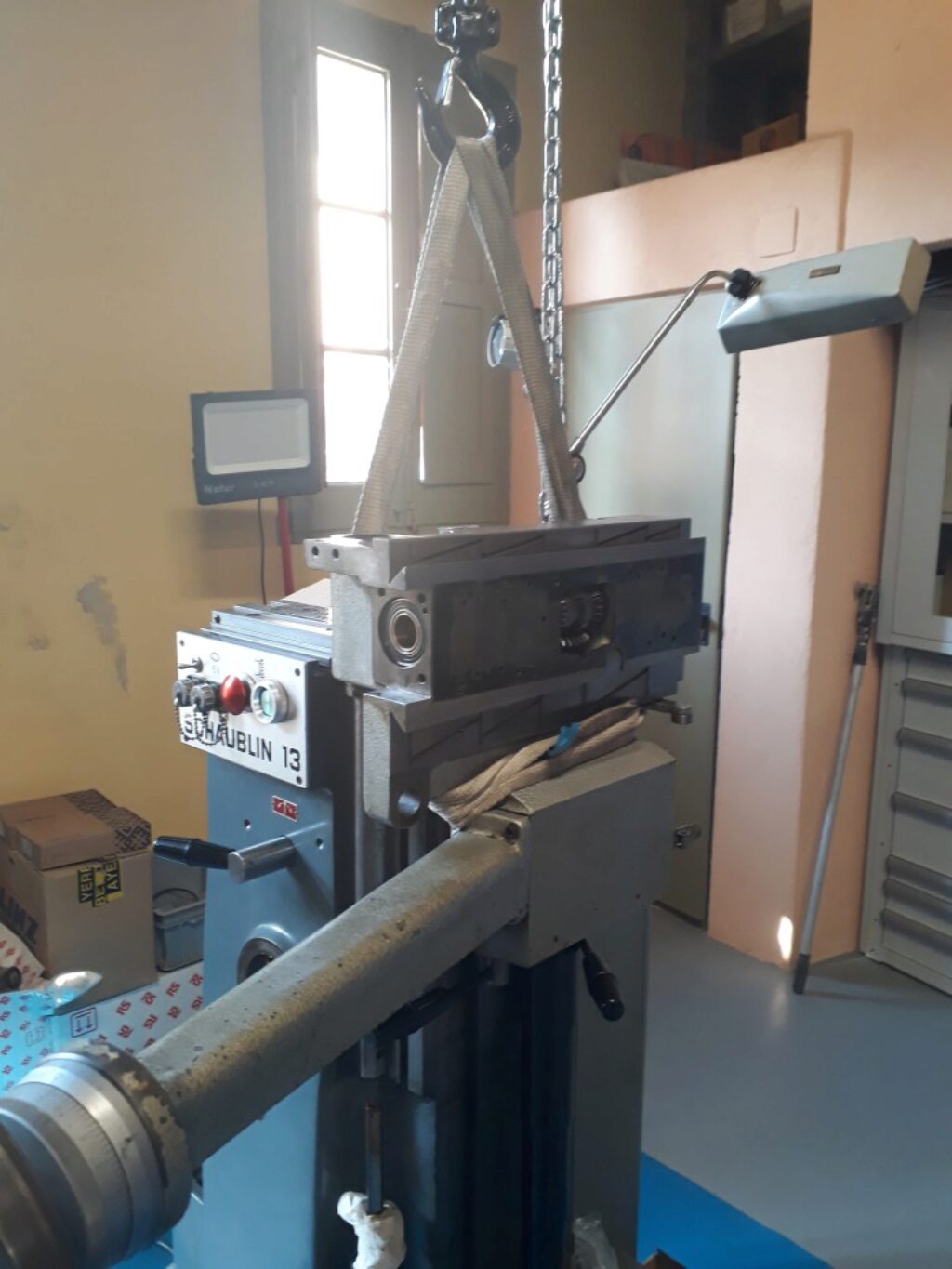
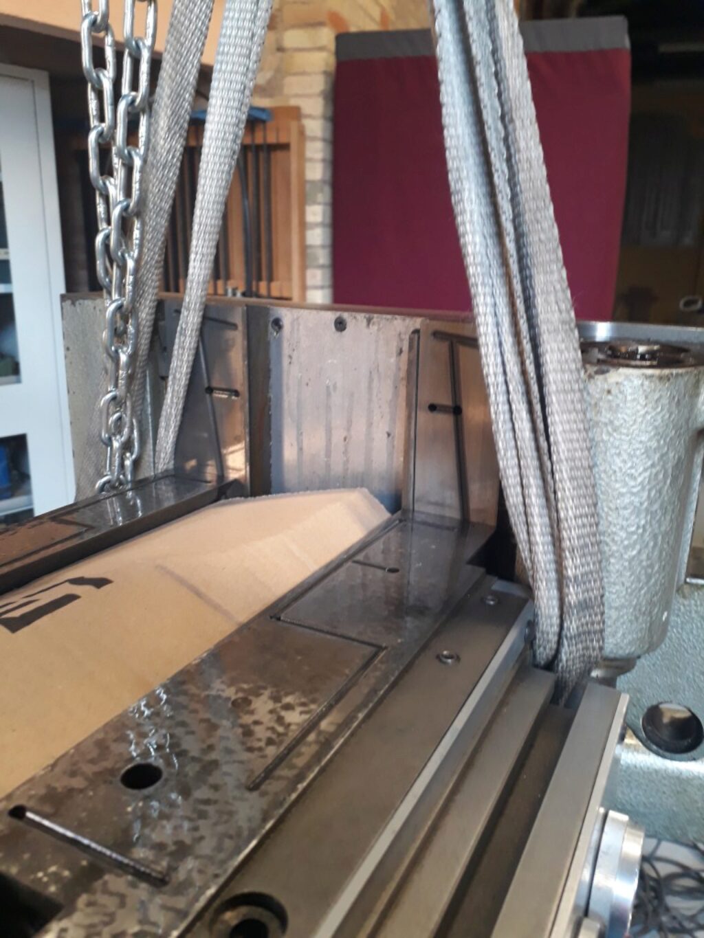
Now, we can pull the table slide after taking apart its wedge. The chain hoist is a good friend:
Disassemble some parts of the knee
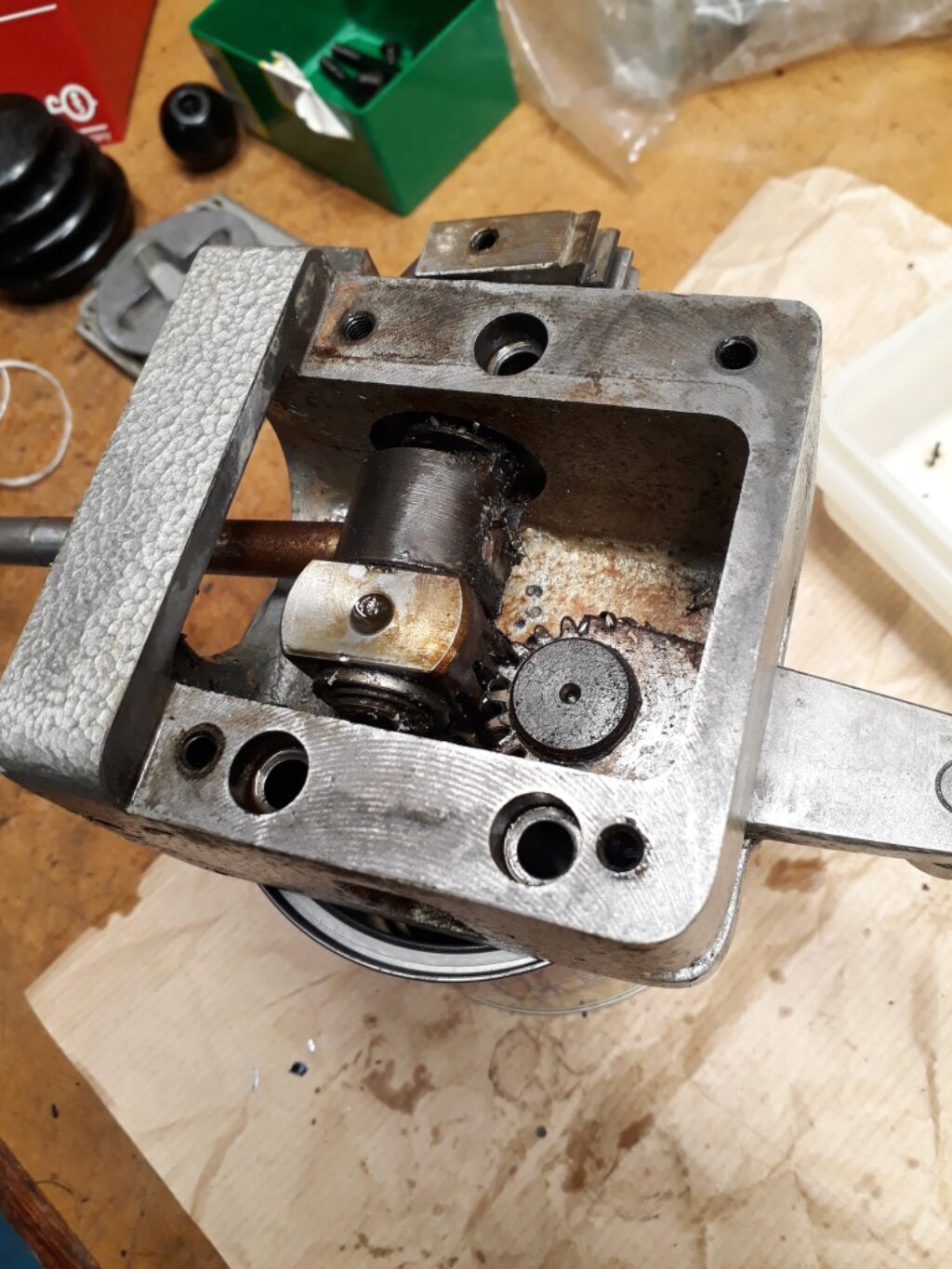
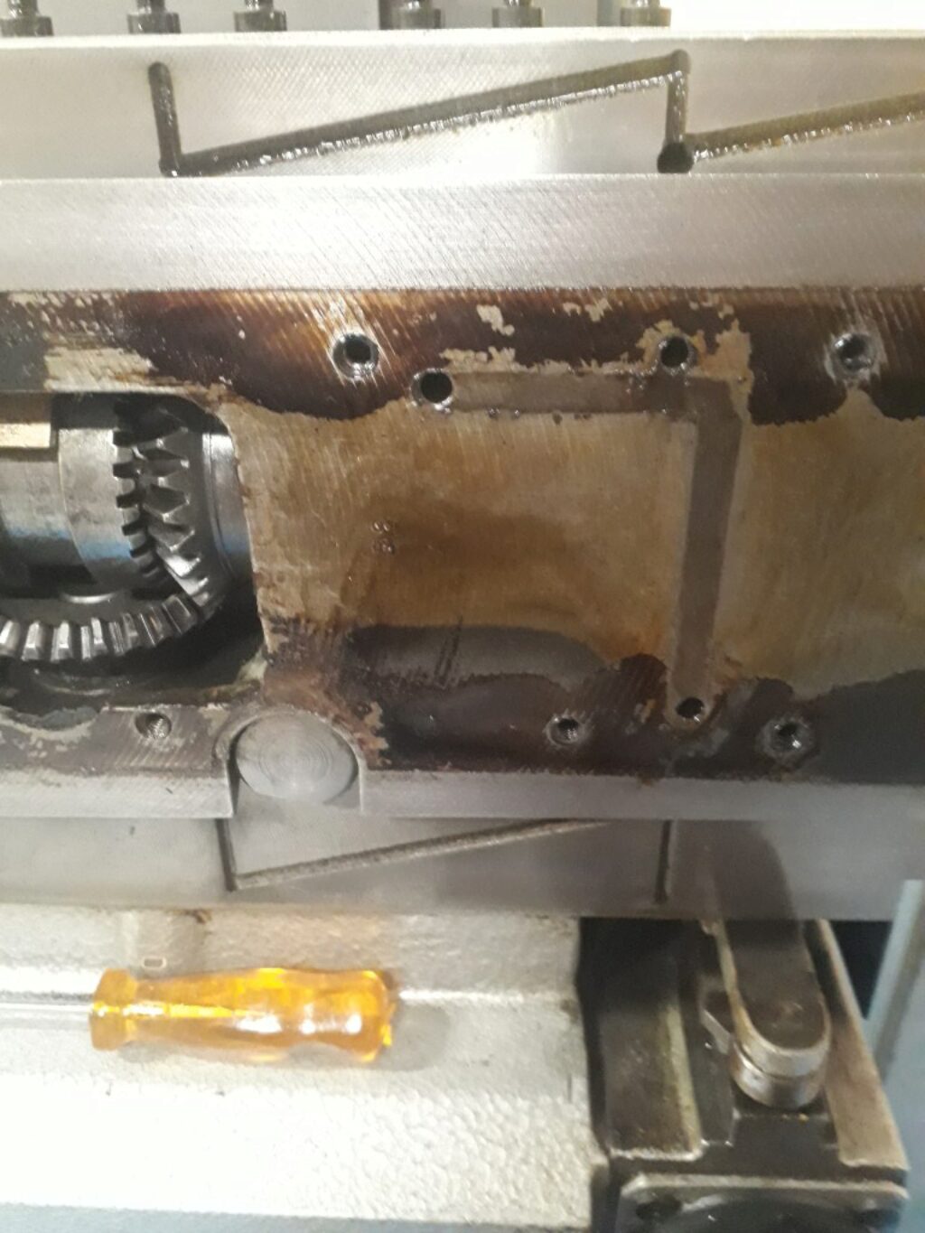
When the table slide is down, it is convenient to set aside some parts of the knee. First, disassemble the traverse handle box. You can also take apart the cover of the feeds gearing in he top of the knee. When this cover is disassembled it reveals the two gears the transmit the power to the knee movement. The right gear includes an overload protection clutch.
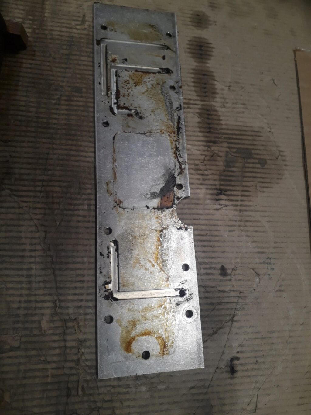
We can also separate the aluminium cover that protects the internal gearing of the knee. Note that this cover is also part of the knee lubrication channels.
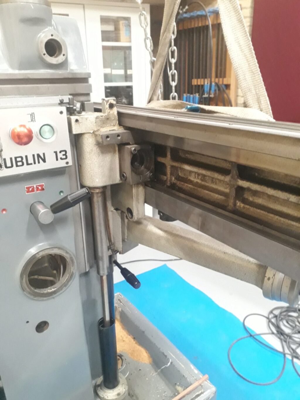
Next step is to pull up the knee with the help of the hoist. First, you should exhaust the Z spindle travel until free. Also, some care should be put on the driving feed bar. It’s easy to do:
The gearbox of the driving feeds
In the tray of the machine there is a cylinder shaped box that protects some gearing related to the traversal feeds. This gearing is the responsible of:
- Output always the same rotation sense despite of sense of rotation of the main motor.
- Give priority to the fast traversals motor when running.
We replaced the v-ring and the small o-rings of the oil circuit.
The traversal feeds transmission
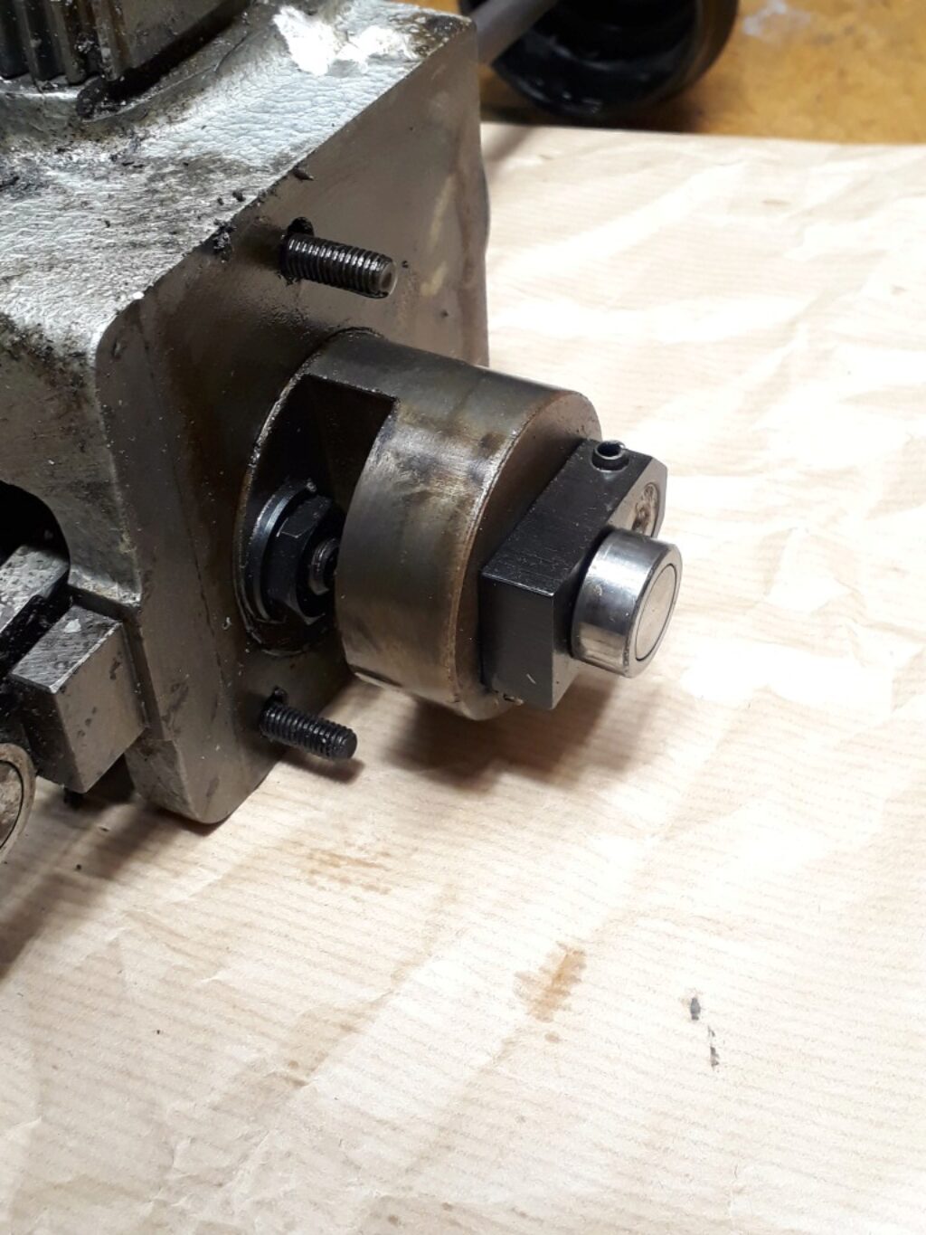
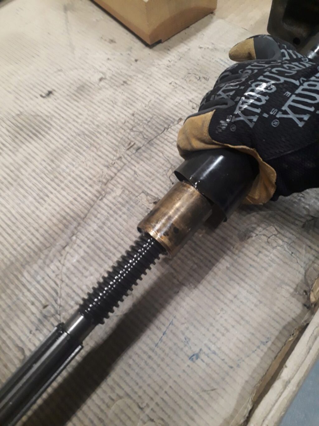
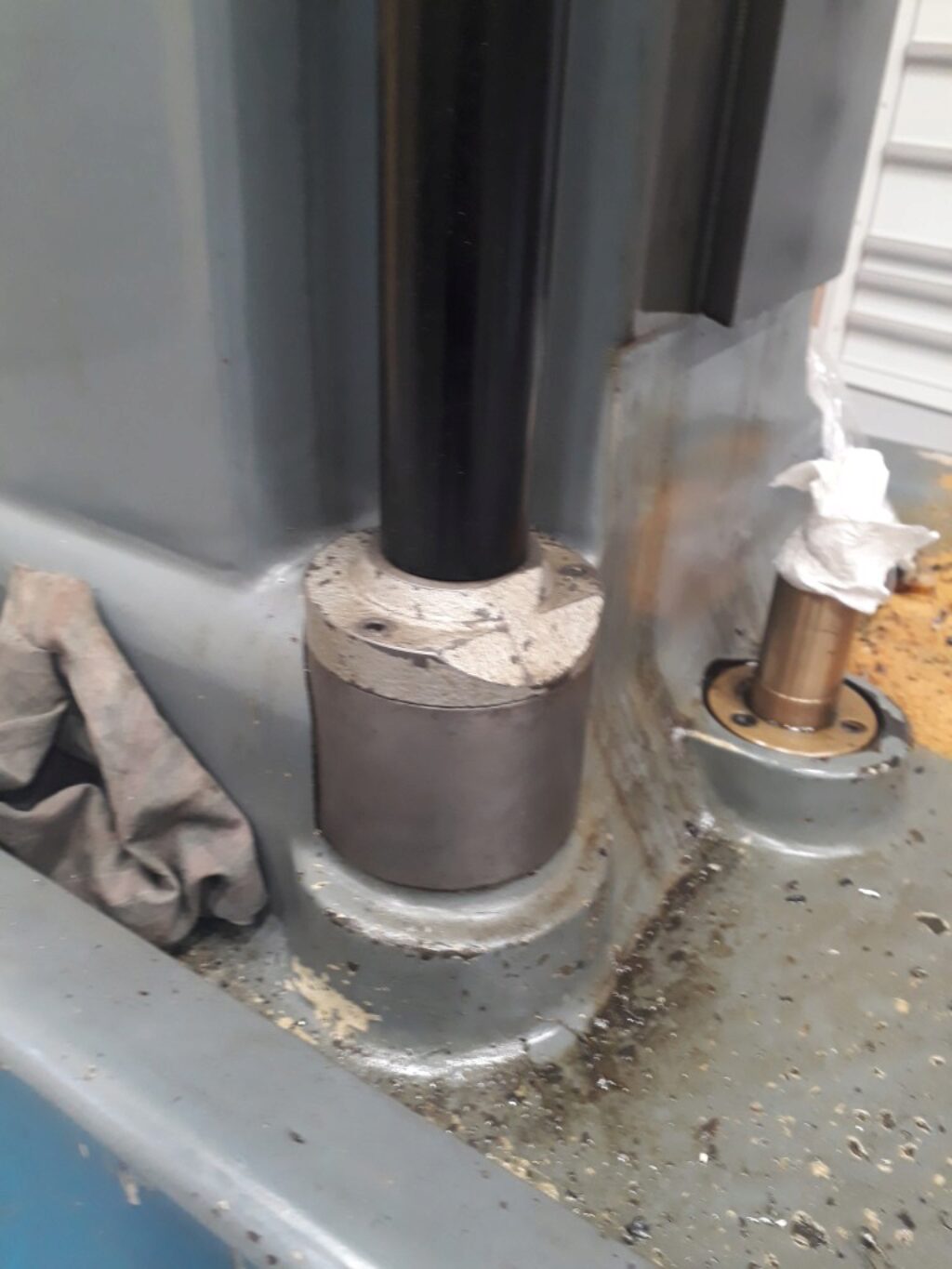
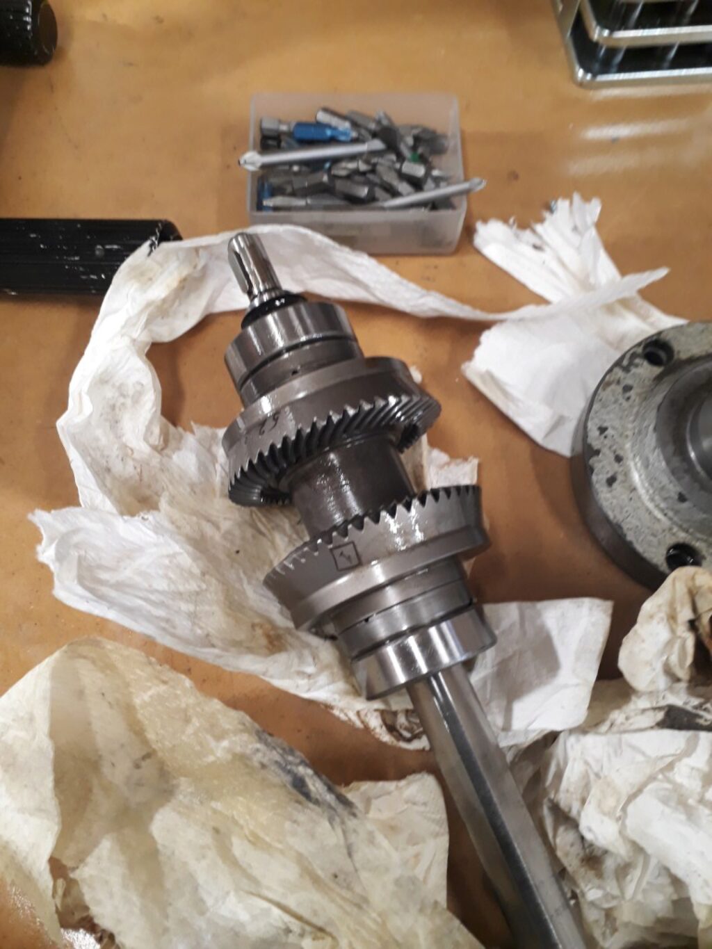
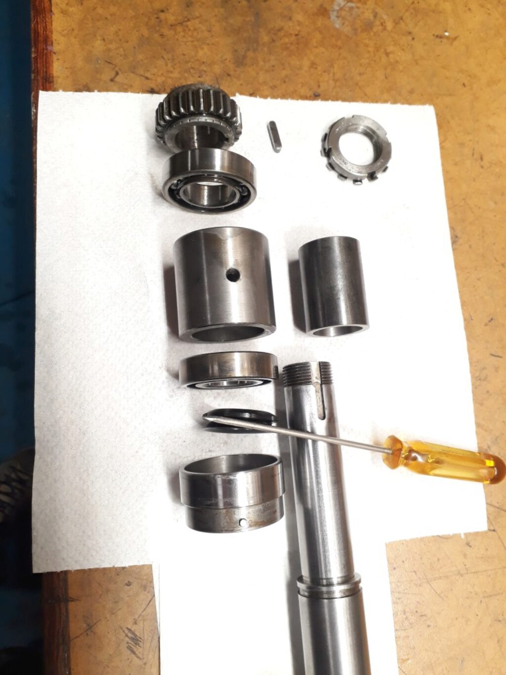
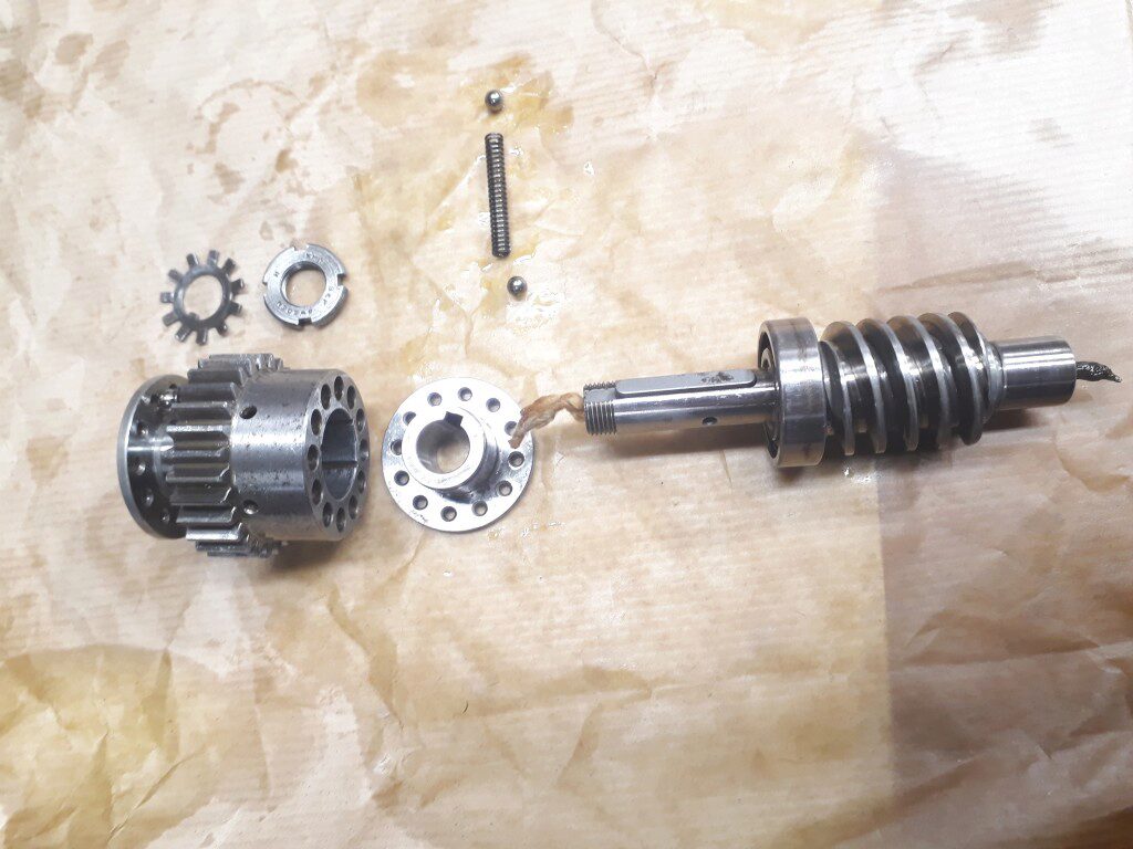
The slides traversal power arrives to the knee by a vertical powershaft that is followed by a couple of gears. The second gear is joined to a worm screw that moves the internal knee mechanisms. In the next pictures you can see the first gear and its powershaft together with its bearings assembly. The assembly is locked by a setscrew to its box.
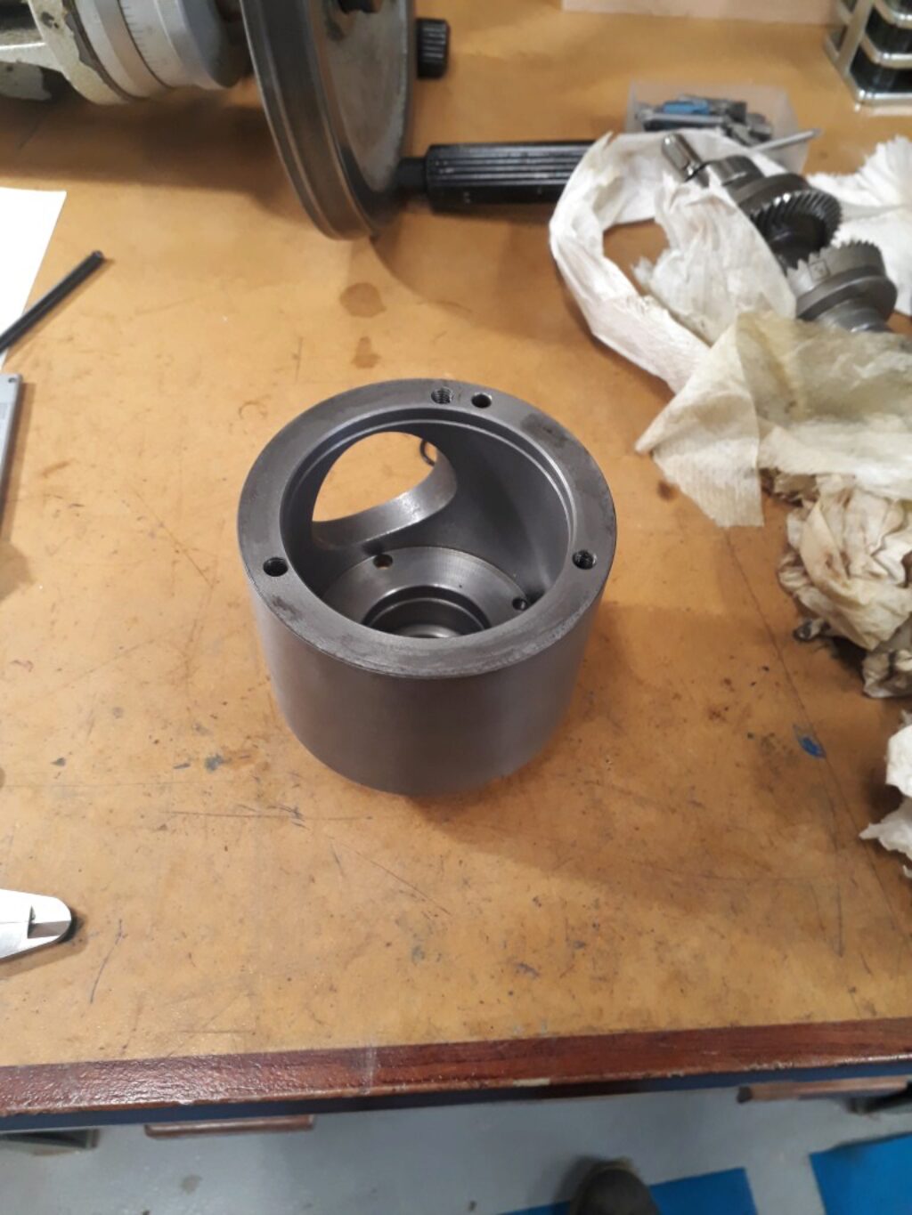
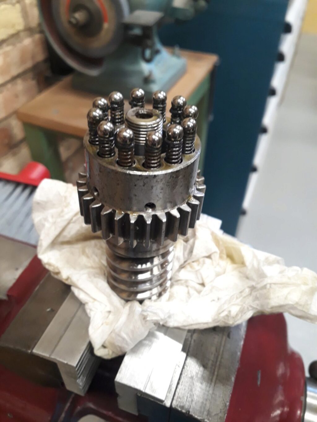
The second gear is more complex. It includes an overload clutch that lets the gear to noisily slide if to much torque is applied.
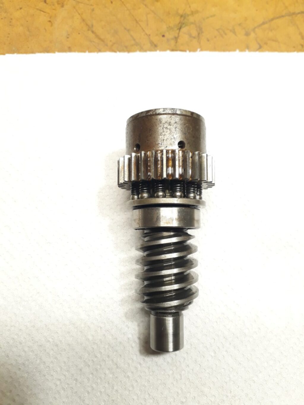
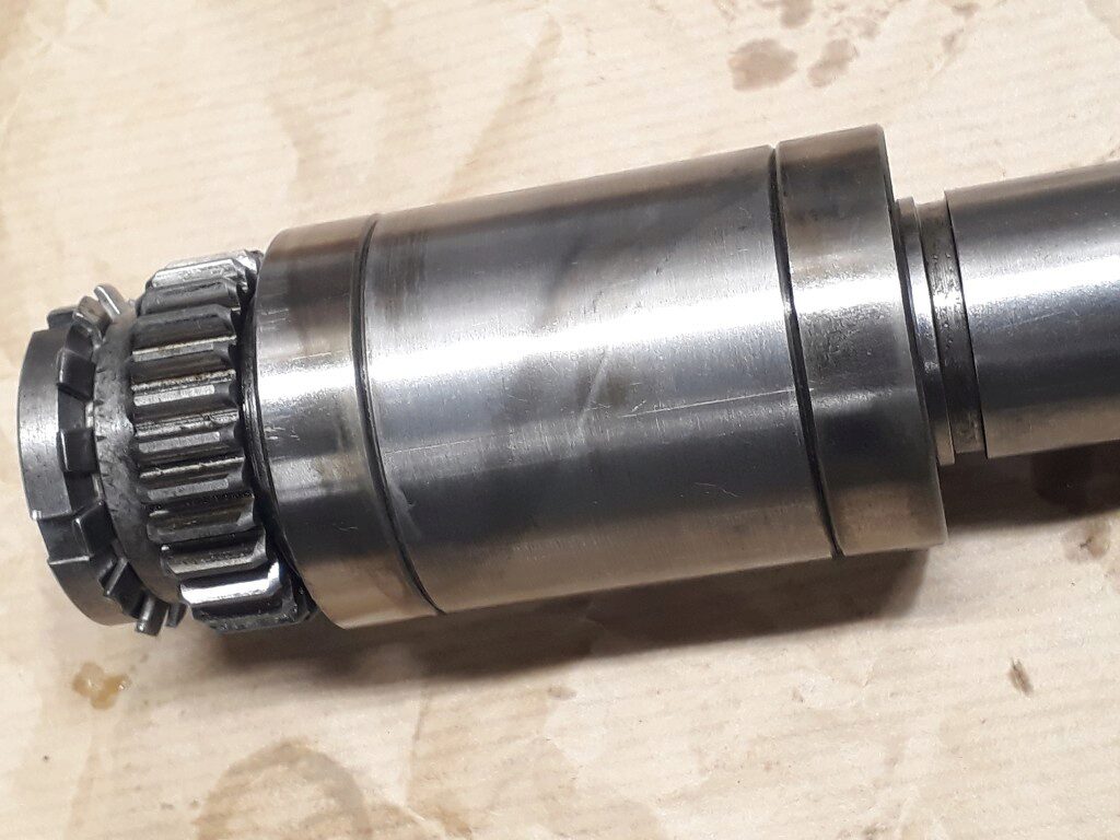
The clutch is made by a set of balls and springs that lock the gear to the shaft through a couple of discs. In the case of excesive torque, the balls slide over its supporting disks. The next picture shows this mechanism:
Note that the shaft is hollow and a wool wick goes through it. Its function is to get oil from the bottom of the shaft —were it accumulates— and get it to the top of the shaft by capillary action. I’m not sure at all of how effective this design is. Most literature I read come from the design of oiling devices for old machines, including old power steam machines. In this literature, the maximum height achieved by the oil on the wick is estimated around 40mm. The shaft doubles this length. However, in the Boley Leinen lathe, this very same resource is used in the threading gearbox and I didn’t apreciate any failure of lubrication.
I replaced the wool wick by a new one. In an attempt to get the best effort, I get no treated worsted wool wicks from Heritage steam supplies.
The reassemble of the clutch was not very difficult:
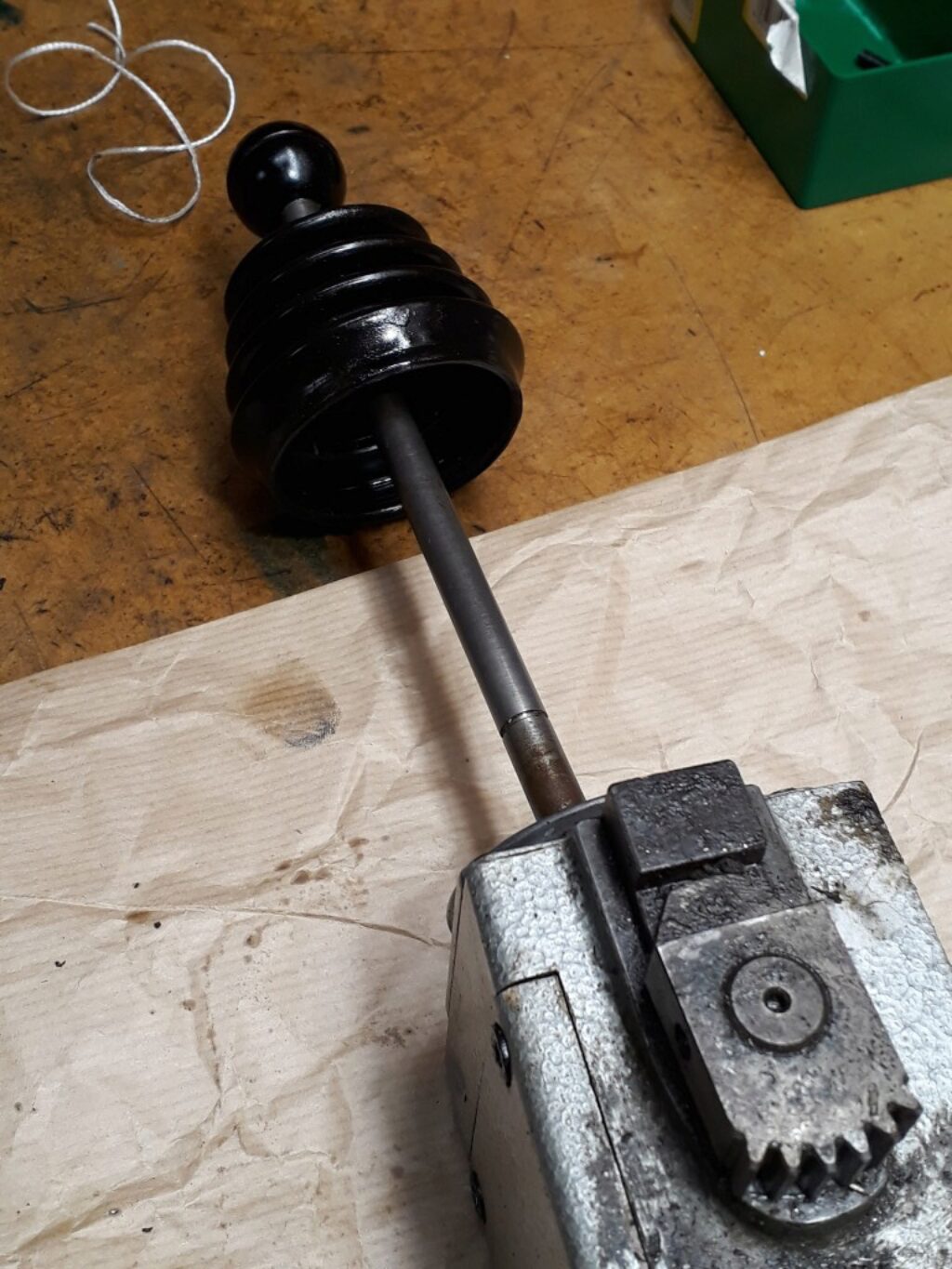
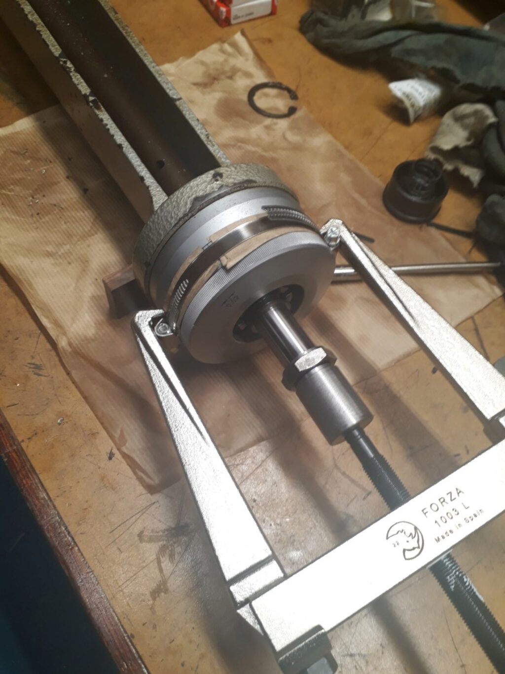
Disassemble the X handle and dial
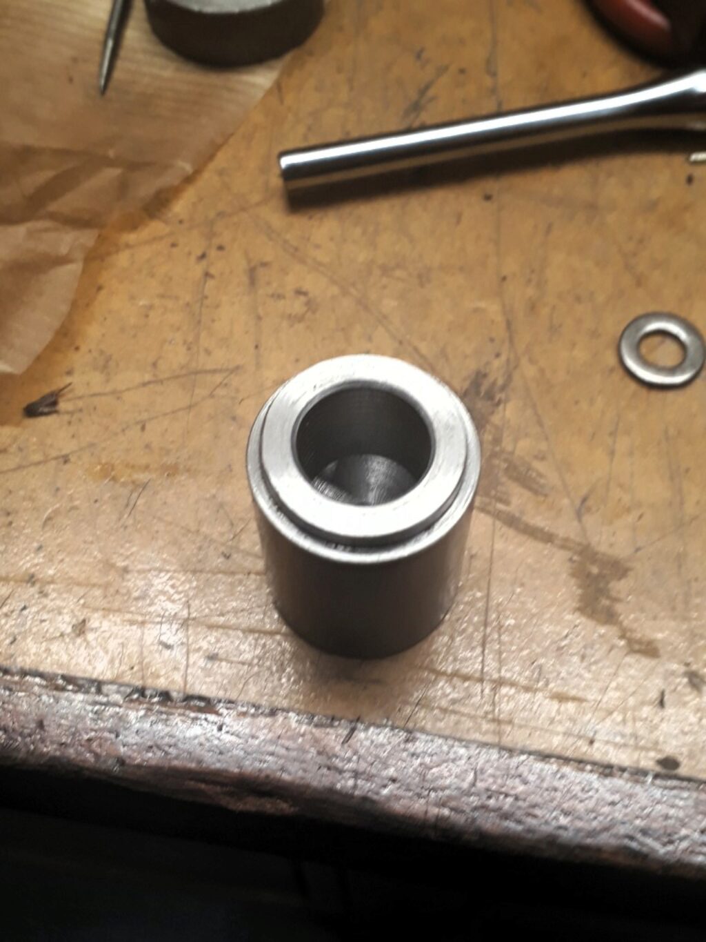
The handle and dial assembly in this machine is rather complex. The locking mechanism of the dial ring goes through the hollow shaft. Taking it out is not easy because of the pressure made by the friction spring. We used a couple of hose clamps and a made to size support as shown in the pictures.
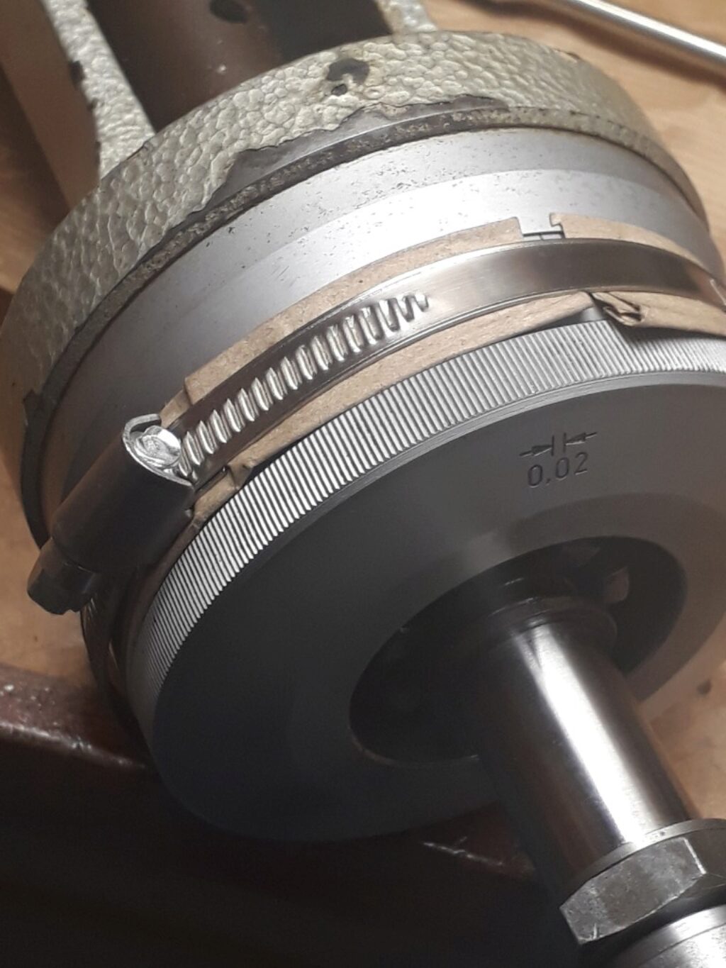
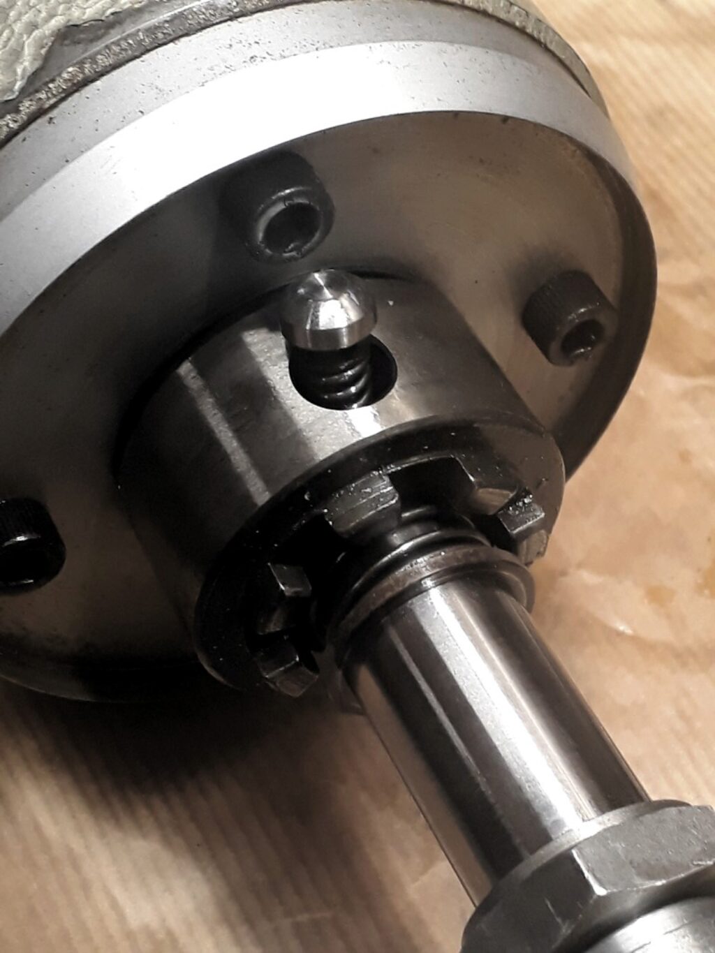
In the next picture you can see the dial journal and the locking device with the friction spring:
Finally, an exploded picture of the handle-dial assembly:

The power feed control lever
The X and Z feeds are controled by a single lever that displaces the internal toothed clutchs. The lever actuates on a clever gearbox that ‘decodes’ the lever movements and translates them to partial gear rotations. The box (a) also assures that not two traversal feeds are active at the same time and, (b) has a couple of small levers that are actuated by the end of course blocks to deactivate the feed. We cleaned and relubed the box.