
The last post discovered the Y axis ram problems. In this post I explain how the aligment problems were (partially) solved. This is the result of a long journey through geometry and aligment testing, scraping learning and lots of patience.
The main conclusions of last post was that the milling machine shows a significative wear on the ways of the Y ram. As a result, the play in the horizontal plane of the ram was sensible and, additionally, an undesired rotation is observed when the Y displacement is reversed.
Scraping practice and basic tools
First action was to gather some new tools and learn to get flat surfaces by scraping. Tools are essential to further investigate were the real problem is in the ram ways. Scraping is essential to get some of the tools at a reasonable price and to refurbish the ways after the issue is well defined.
I will avoid the details of all the stuff concerning scraping practice in this post and write a specific post in some weeks.
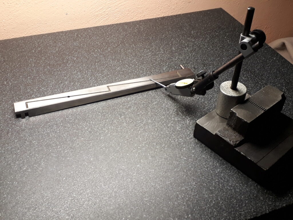
Finally, after some months, I ended with a slight experience in scraping and some useful tools. Mainly a precision surface plate, a magnetic master square, some straight edges, scrapers, scraper grinding tool, and spotting ink.
First tests with the new tools
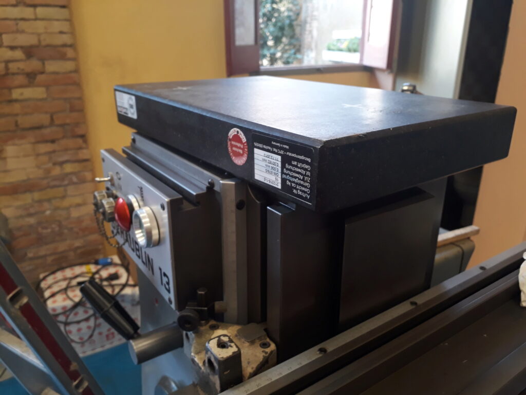
The first test concerned the orthogonality of the Y ways with the Z. Using the magnetic master square this was easy to check:
The result was the ram is climbing 0.01 mm over the square plane defined by Z ways. This is uninteresing. In fact, if the ram had beed sagging 0.01 mm —instead of climbing– would have been much better.
Thus, there are also some wear on the flat part of the Y ways. It would be miraculous that flat parts of the way were pristine while the dovetail flats were weared.
To add information a new test is made. A small surface plate is blued with spotting kink and the flat static ways spotted as shown in the next picture:
the result obtained is this:
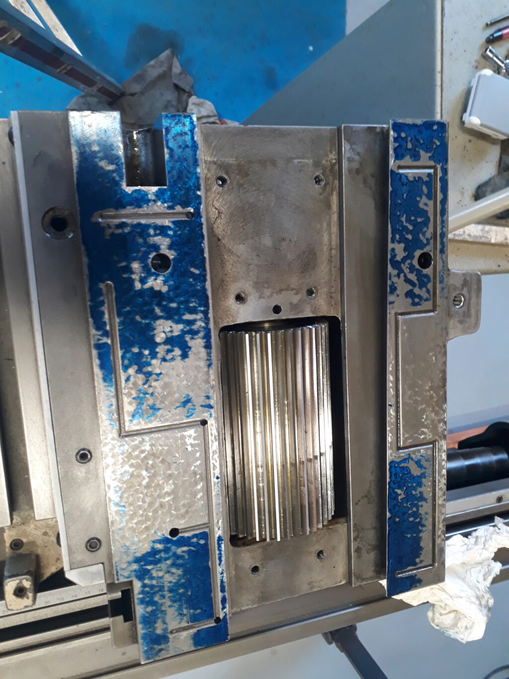
Note the following:
The original scraping marks are clear and correspond to a classical european technique: “grattage a l’épaule”. Most of swiss machines are scraped using this technique.
It’s is clear that the central part of the guides are scraped slightly deeper. This is an usual and reported technique in the literature. The shorter part of the ways could be scraped following this pattern. The central part is depressed an small amount, say 0.005 mm. First, the depressed part acts as an oil reservoir that results in a better oiling of the ways. Second, the ways should work on its ends to achieve the better support of the ram. Considering that a perfect plan is impossible to achieve, is better to depress the center to avoid a convex profile that would be unstable.
Note that the left (in the picture) flat is much wider than the right. This is the flat that has the screw slot. This slow reduces the supporting surface. This was compensated by designing a wider flat.
The spotting shows a contact that, although no perfect, could be good enough. The greatest wear is in the back part of the guides. This surprised me but is consistent with the climbing that exhibits in the previous test.
The next test was to check the dovetail of the ram. Using the angular straight edge conveniently inked the result is shown in the next picture:
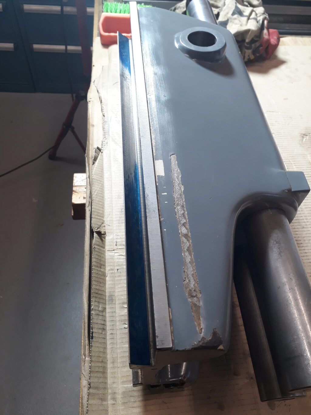
The result is clear. There is a considerable wear on the central part of the dovetail. The result for the other side was similar to this one.
I also checked the static part of the dovetail an the gib (see picture below). The result was that both gib and fix dovetail follow the “center depressed pattern” as seen on flats and both showed some degree of wear as expected.
From all this information I designed the next workplan.
Workplan
I followed this workplan:
Above all do not exhaust the adjusting capability of the gib. Every time you reduce the thickness of an element by scraping it, you will need to increase the gib action. The gib, however, have a limit to compensate the scraped elements: about 10mm of lineal movement at its maximum, what means approximately 0,12 mm of dovetail thickness. If while modifying geometry this limit is surpased, a new gib would be necessary. I didn’t want to fit a new gib. Thus, this sets a limit on all the procedure.
Mostly ignore the flats. From the tests, the main wear comes frome the dovetail. Then, sacrifice the flats perfection to favor the gib conservation. At most, lightly scrape the static flats to increase the contact points in the ends of the guide.
Try to reduce the wear of the ram dovetail. Maybe, to save the gib, allow a small imperfection on the deepest wear point if this do not influences the ram displacement quality.
Scrape the dovetail static part to achieve a depressed middle an a nice ends contact.
Maintain a very good paralelism with the shaft of the machine and reduce as much as possible the play in the horizontal plane of the ram.
Results obtained
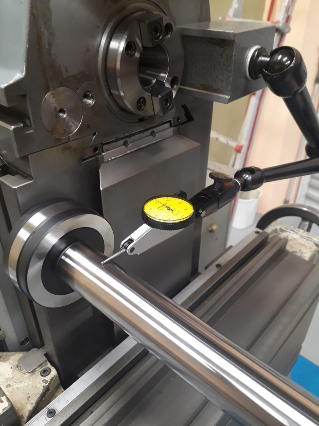
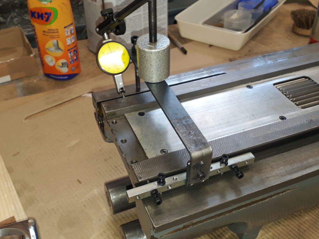
The dovetail of the ram has been scraped until obtaining a new surface. Most of the worn part has been overhauled. The gib advanced about 4 mm and maybe 4 mm more are available for future adjustments. To check the parallelism of the ram dovetails, a gig shown in the next picture have been made. Note that measuring using pins is not possible due to the slot that contains the feed screw (slightly visible on the farthest flat).
Play in the horizontal plane has been reduced to 0.002 - 0.004 mm range. Play when changing the displacement direction of the ram amounts 0.01 mm at most. Parallelism of ways with the machine shaft is in the range 0.002 - 0.004 mm. Squareness of Y and Z has not been modified and remains an error of 0.01 mm.
The following vids show the current play when changing direction. First in 1/100 mm and after in 1/1000 mm.
The condition has been vastly improved on the horizontal plane while on the vertical plane the error remains. This is consistent because the flats have not been scraped.
I didn’t find a way to go further. My guess is that without work on the flat parts of the ways is difficult to obtain better results because of the influence of the flats on the dovetail adjustment. I do not reject to work on the flats in a future.
A fascinanting question about geometry
Assume that the Y ram is a 2-dimensional mechanism and that there is no way to get a perfect fit of the ways. Then, because the push/pull action of the feed screw i asymmetrical, a rotation of the ram exists when changing feed direction. Consider the next drawing:
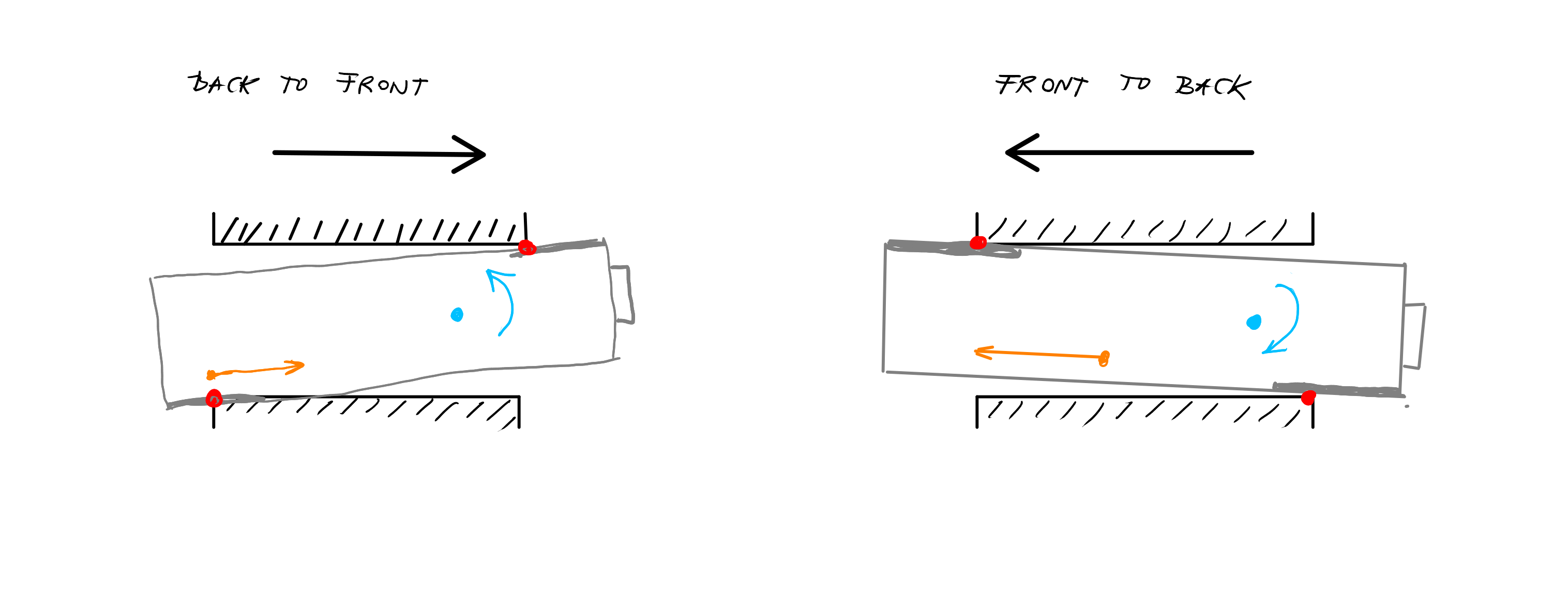
On the left figure, you can see the ram position when moving back to front. The feed screw action is represented in orange. In blue, you see a tentative center of mass and the rotation induced by the feed screw action. Thus, the contact points of the ram on its guides are the red dot and the ram should mostly glide by the thicker grey line. The right figure shows a similar situation when ram is moving front to back.
Note that when you change the ram direction, a rotation appears that goes from the current situation to its complementary. This is what is observed when measuring.
Assuming this behavior, how much can be reduced this measured rotation?