In this post I talk about the maintenance of the Schaublin 13 table feed gearbox. It is easy to identify because it protrudes the back of the machine in an unusual way.
The Schaublin 13 has a range of automatic table feeds on the X and Z axis. While feeds are commanded from a kind of «joystick» on the console front, the speeds gearbox is located on the machine back as you can see in the next picture:
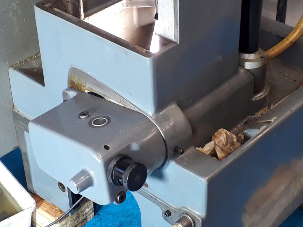
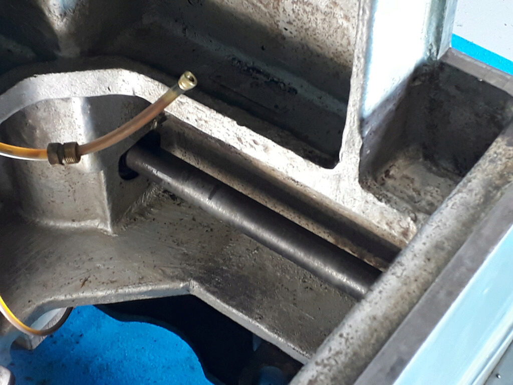
Note the black knob: it’s used to change the feed speeds of the table movements. It has two ranges and a number of speeds in each range. In the machine, the knob appears full of oil. Thus, I wanted to check it. The gearbox gets power from the main motor through a vee belt and feeds the milling machine console through a shaft that ends in a bevel gear. In the last picture, you can see the curved form of the machine main shell that protects the power shaft. Seen from the interior this is the shaft:
And this is the gearbox pulley —that is belted to main motor— while being pulled off:
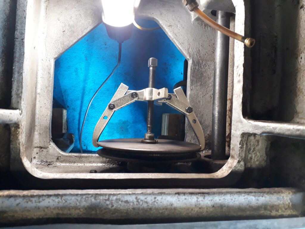
The gearbox rotates around the power shaft axis. This movement allows to tension the motor belt. This can be seen on the first picture.
Dismantle the gearbox
To get the feeds gearbox out of the machine you should first drain the oil. Surprisingly, I discovered that the gearbox was exceedinlgly full of oil. I almost recovered 1,2 l of oil. The manual states that you should fill it with 0,5 l of oil. This was good news: probably it’s the reason because oil spills out by the knob.
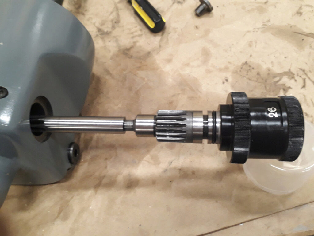
After that, you should pull off the pulley. This pulley is maintained in his shaft by a special locking screw. First you should unlock the screw by loosening the central Allen set screw, after that the screw can be unscrewed using a c-hook spanner and the pulley pulled off. Once the pulley is out just unscrew the gear box and pull it at hand to get it out of the milling machine.
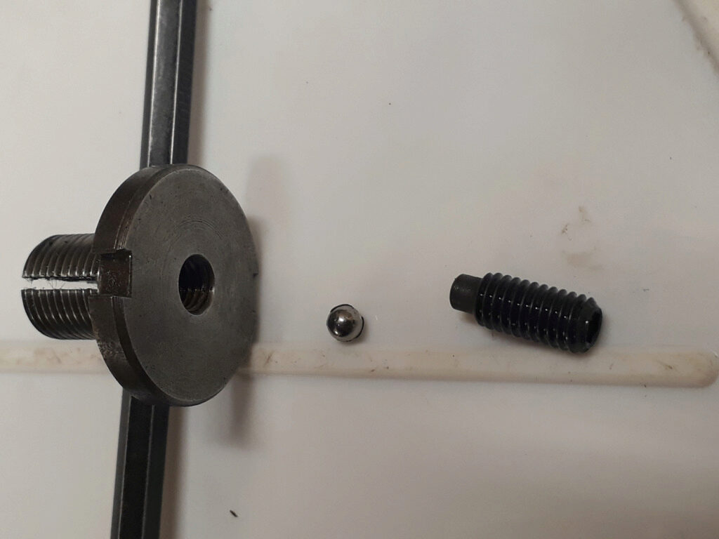
The following picture shows a detail of the special locking screw. The stell ball pushes the screw interior, expanding the screw diameter and locking it:
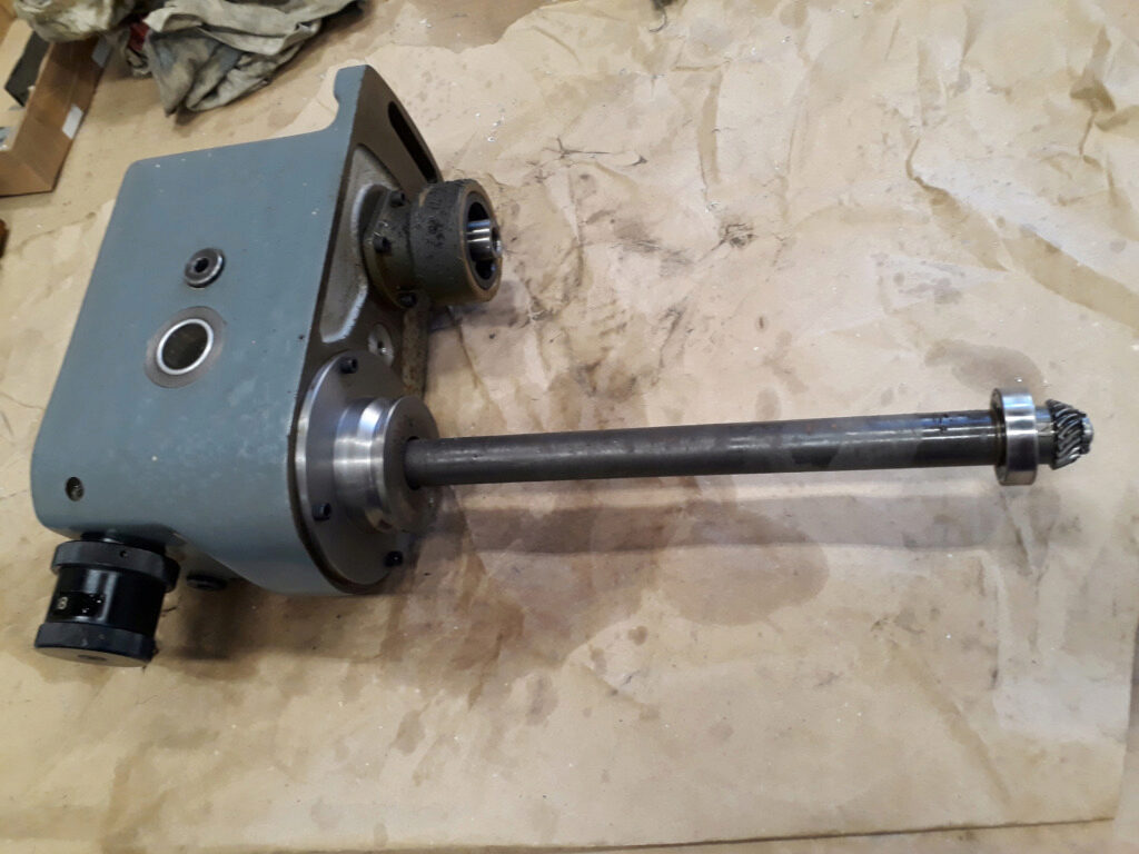
The gearbox after being pulled out:
Service the knob o-ring
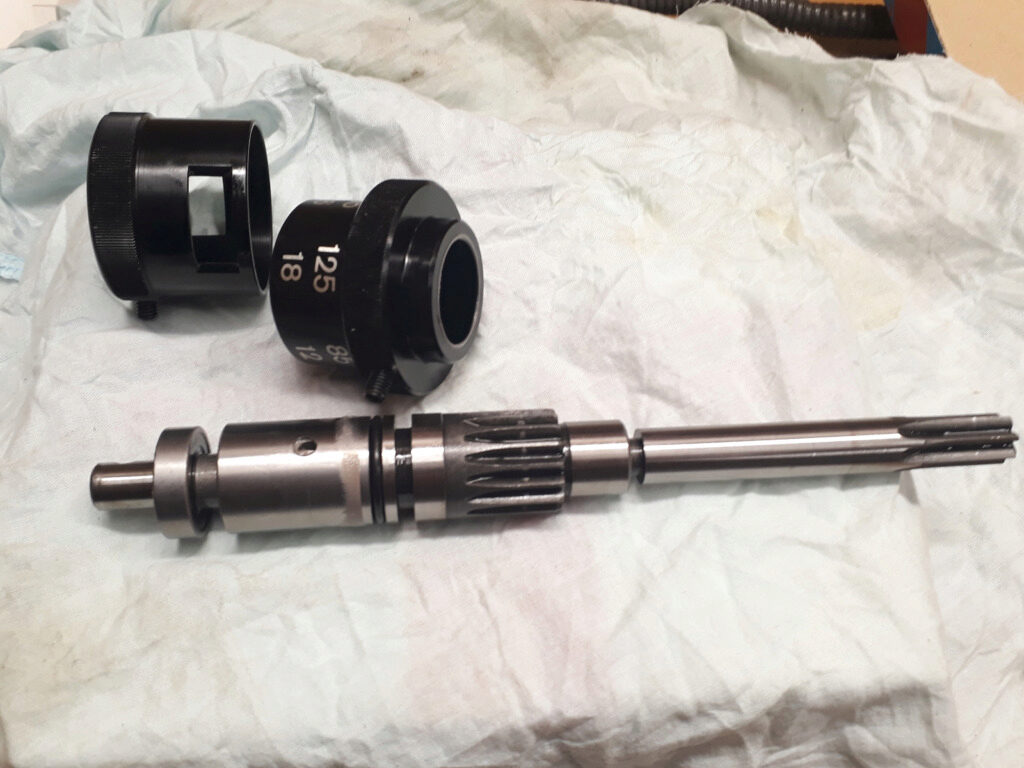
The knob shaft is easy to pull out: just unscrew the retaining set screw and pull the knob apart. The knob is mounted over a double shaft to actuate over the two speed ranges. This is an exploded picture of the knob-shaft assembly:
The current o-ring was of size 23 x 2,5. However, the Freudenberg calculator gives a thicker dimension. I replaced it by a new o-ring of the same dimensions that the current one. It is on smooth fit range but could be enough. The next pricture shows the knob assembly being pushed again into the gearbox: