
In this post I show the maintenance of the Schaublin 13 Reeves drive. Together with the main gearbox, it constitutes the milling machine power drive. You will see how I dismantle, clean, examine and service it.
Belt variator drives, also known as Reeves (after Milton Reeves) or Variable-Diametre Pulley —VDP— drives, are usual on conventional machine tools. They allow to continuously change the rotation speed thus offering an infinite set of speed unlike change gears. This also the case of the Schaublin 13.
The implementation of the Schaublin 13 VDP has two fixed diameter pulleys, on the motor and the gearbox, and a third double variable diameter pulley in the middle. This middle pulley has a support that moves it up and down. While the central pulley moves up and down, the center to center distance between pulleys changes and this forces the central pulley to change its diameter. The central pulley shaft is displaced by a robust mechanism through the external speeds handle.
Central pulley support
The central belt shaft is supported by a mechanism that allows it to be displaced vertically. This mechanism is mainly a big cilinder that slides on a couple of supports by means of a screw. The screw is actuated through a bevel gear by the external handle. The cylinder can be locked in its position through a partially split housing and a bolt. The folowing two pictures show this support after being throughfully cleaned.
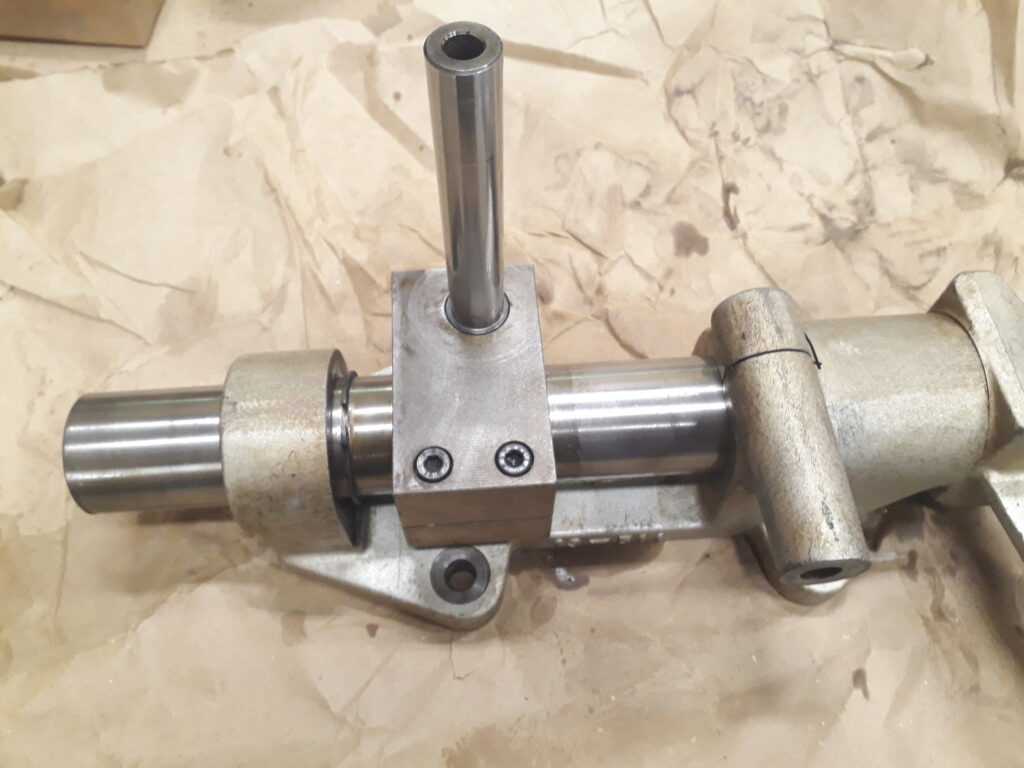
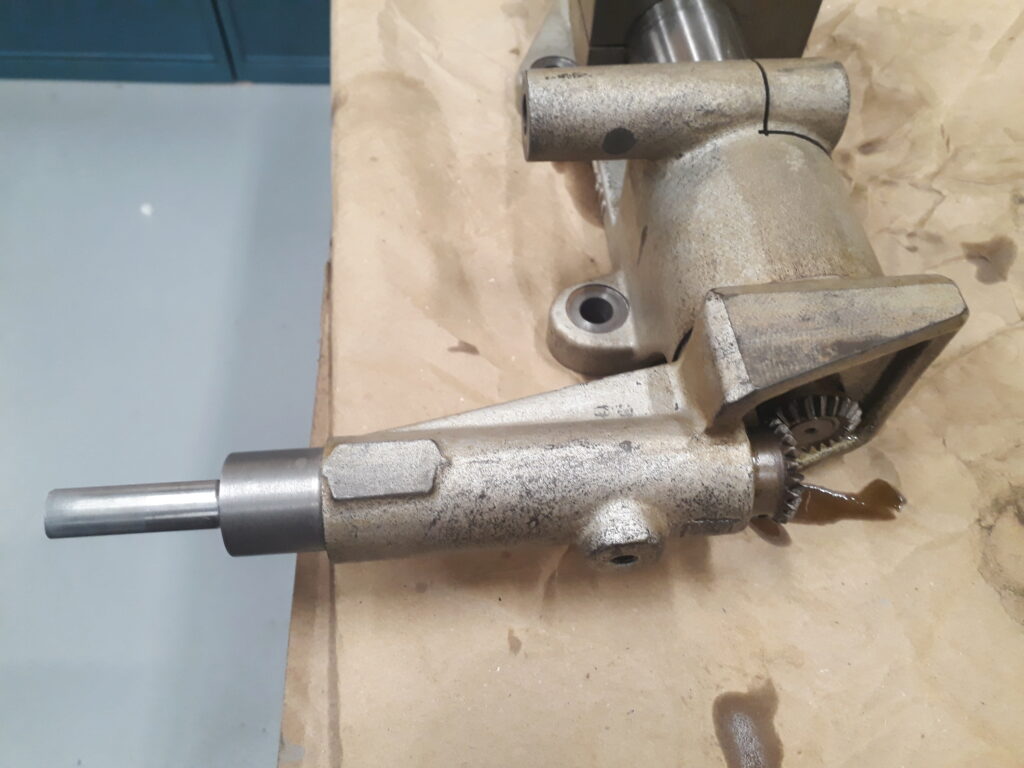
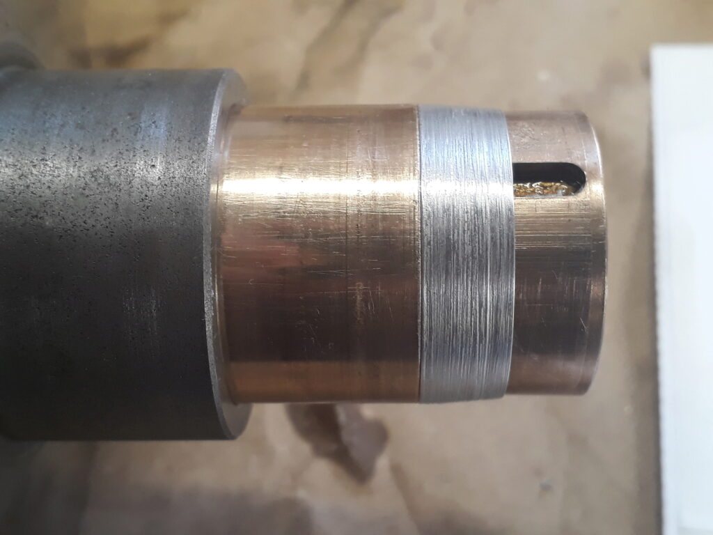
Note the superb finish on the bearing shaft. It is through its central bore that oil comes to the bearing. The handle shaft is lubricated by the central lubrication system and a part of the oil going out of this shaft falls over the bevel gears and accumulates on a small oil sink on top of the mechanism top. This sink can be seen in the next picture:
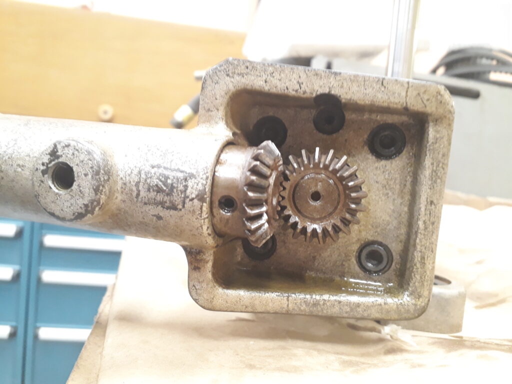
Note that (on top of the picture) the sink has a small hole that drains the sink oil over the supporting cylinder and the screw (covered by the cylinder and not seen in the pictures). Overall, an ingenious way to lubricate all the mechanism.
The journal bearing of the pulley gets its oil directly from the lubricating oil tank. It’s interesting to note that bearing oil do not arrives through the lubrication hand pump circuit. Bearing oil flows permanently by its own weight through a dedicated line.
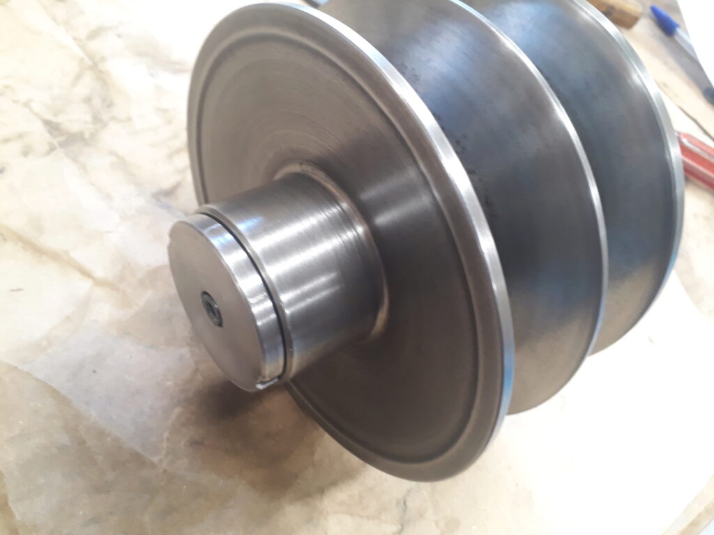
Central pulley
This is a double pulley with a sliding middle part. When one of two grooves widens the other is stretched and the drive changes its relation.
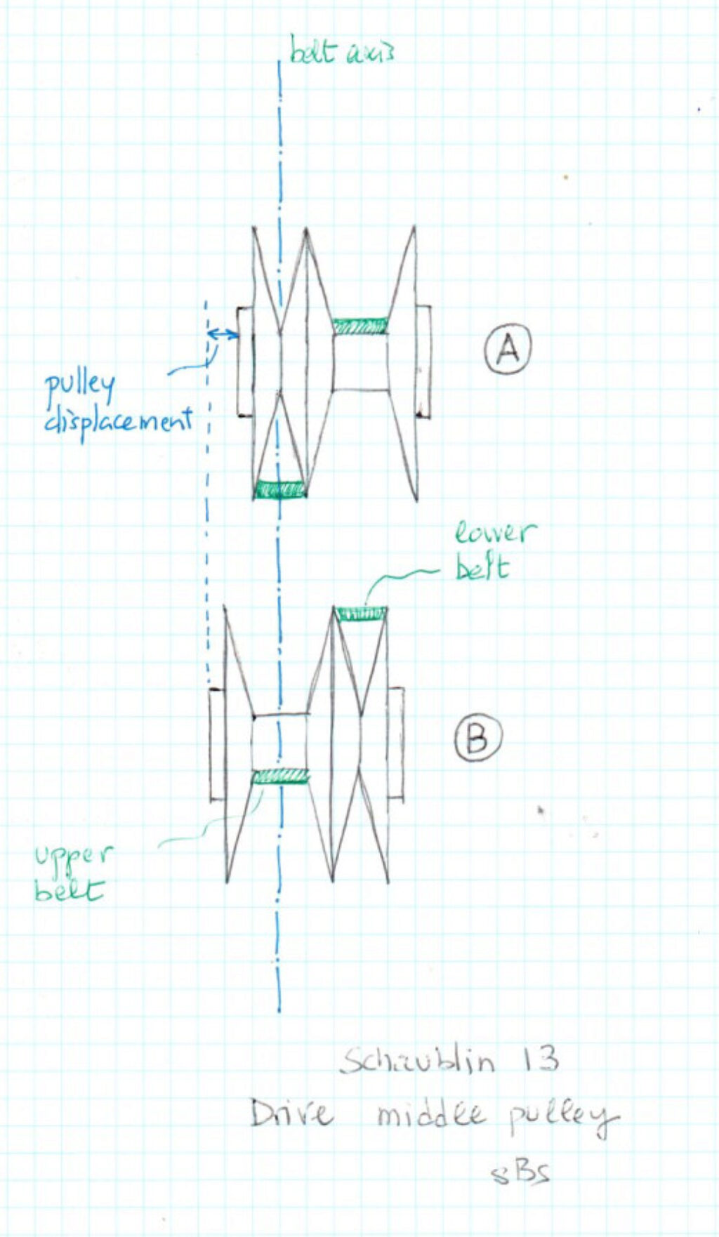
Surprisingly, the central pulley rotates over an hydrostatic plain bearing permanently feeded by oil. In fact, because of the pulley design, when the diameters change also changes the belt axis and thus, the pulley needs to allow for a slight axial displacement. This is, probably, the reason because a plain bearing is used. The next figure shows this effect. When pulley is in position A (up), the upper belt centerline is as shown in the drawing. When pulley is moved to position B (down) pulley should be axially displaced to the left to maintain the same belt centerline. Note that belt centerline is constrained by the fixed position of the upper pulley (not shown on the drawing). The axial displacement amounts approximately half of the belt width.
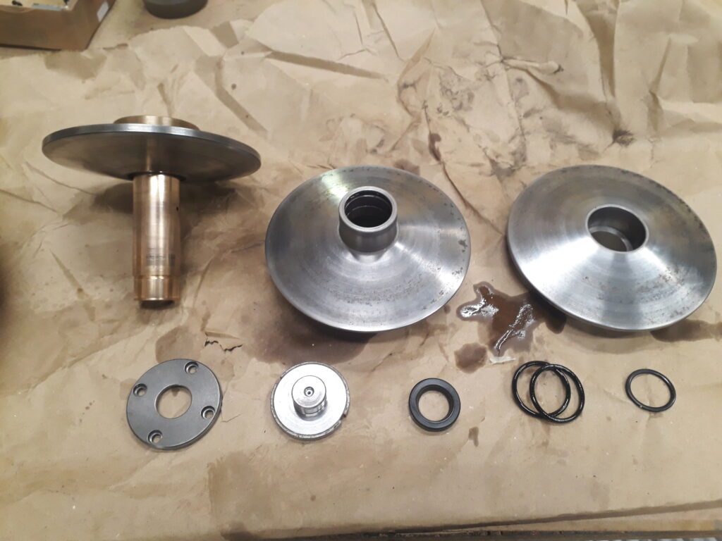
The middle part slides over the bronze bushing exterior and oil becomes enclosed by two o-rings. The bronze bushing interior implements the hydrostatic plain bearing. A lip seal avoids oil flowing out the bearing. In the picture below you can see all the parts that are included in the central pulley.
To service the pulley, the o-rings and the seal should be replaced conveniently. A problem arouses with o-rings: the maintenance manual do not specifies its size. This is specially critical for the sliding part o-rings. Other people, manly in the french forum Passion Usinages, give some temptative sizes. However, I used the o-ring calculator of Freudenberg. After feeding it with the needed dimensions and type of sealing, the result obtained suggested an o-ring of 33,5 x 3,5 mm.
The seal referenced in the maintenance manual was of an older type difficult to find. Someone, in a previous service, did a good job modifying the seal seat to receive a more standard modern seal. Look at the next picture:
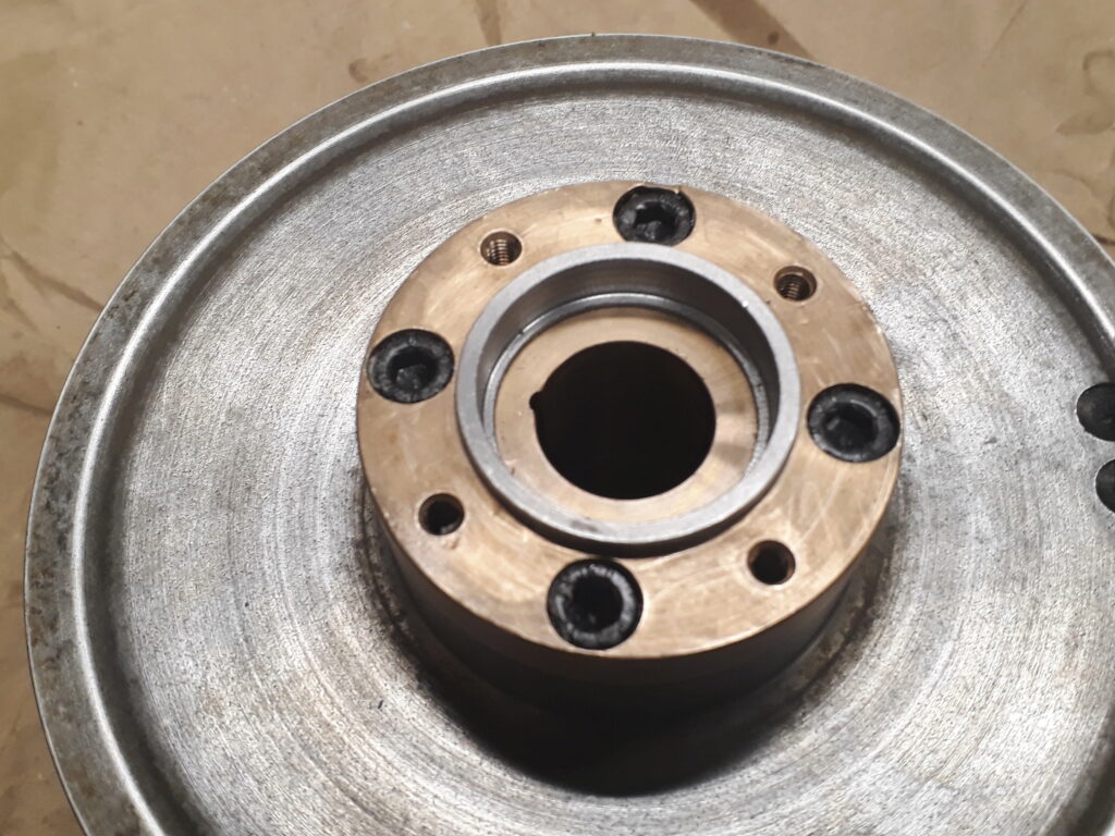
With this repair, the seal needed is a single or double lip 22 x 35 x 7 seal. I replaced it by a Simmerring BASL 22 x 35 x 7 of NBR 72.
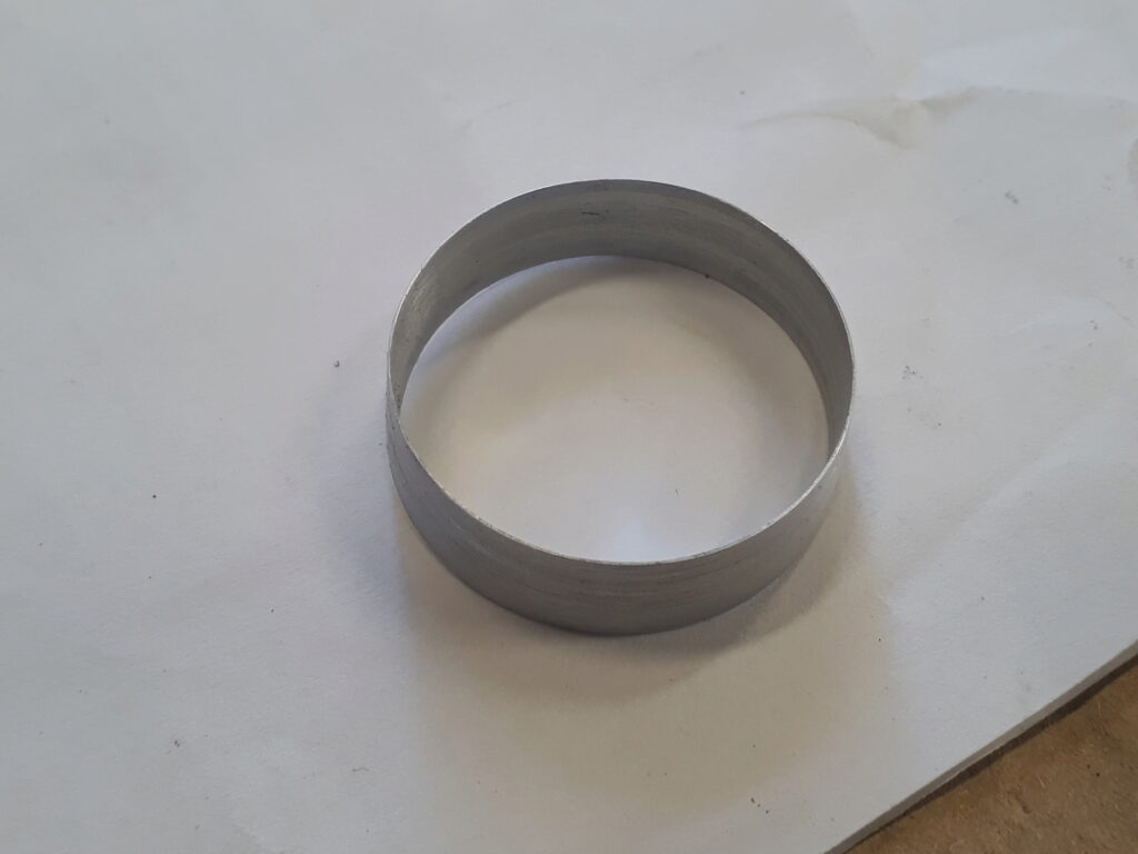
To mount the sliding middle part with the new o-rings I made a jig to save the shaft step and do not dent the o-rings. The next pictures show the gig.
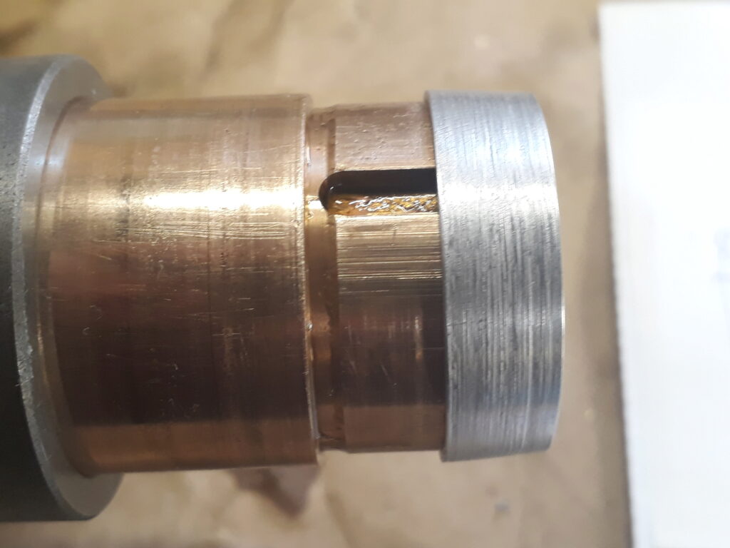
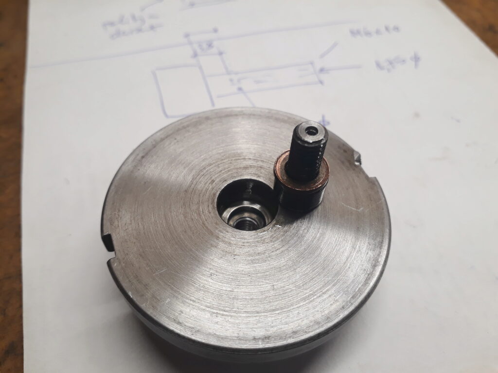
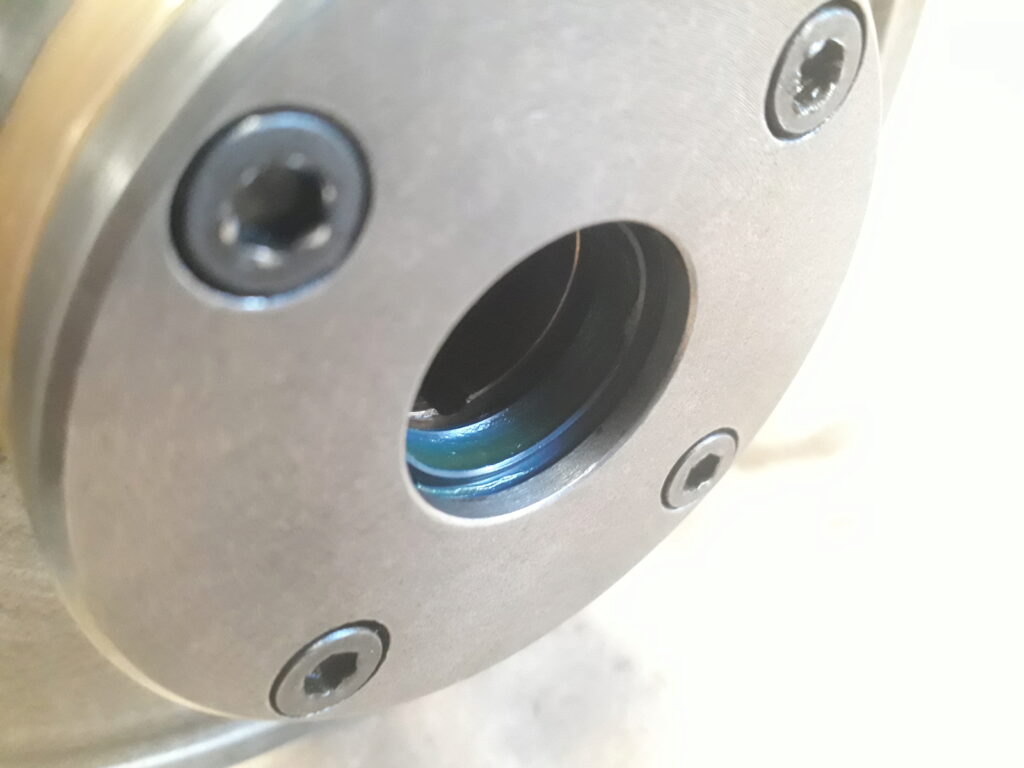
In one of the axle ends, there is an special plug sealed with an o-ring of 27 x 2,5 mm. This plug has a suspicious allen screw in the center that, when loosened, split in two parts :sad:. It seems to me that it was abused time ago. I managed to get out the screw from the plug and discovered that it is really a mechanized screw to act as a valve. I made a new replacement as you can see below.
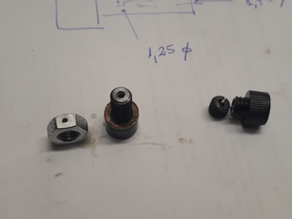
When you slightly loosen this screw, its small bore allows air on the bearing inside to go out. I guess that this is its utility: to allow air go out while fitting the pulley into its shaft.
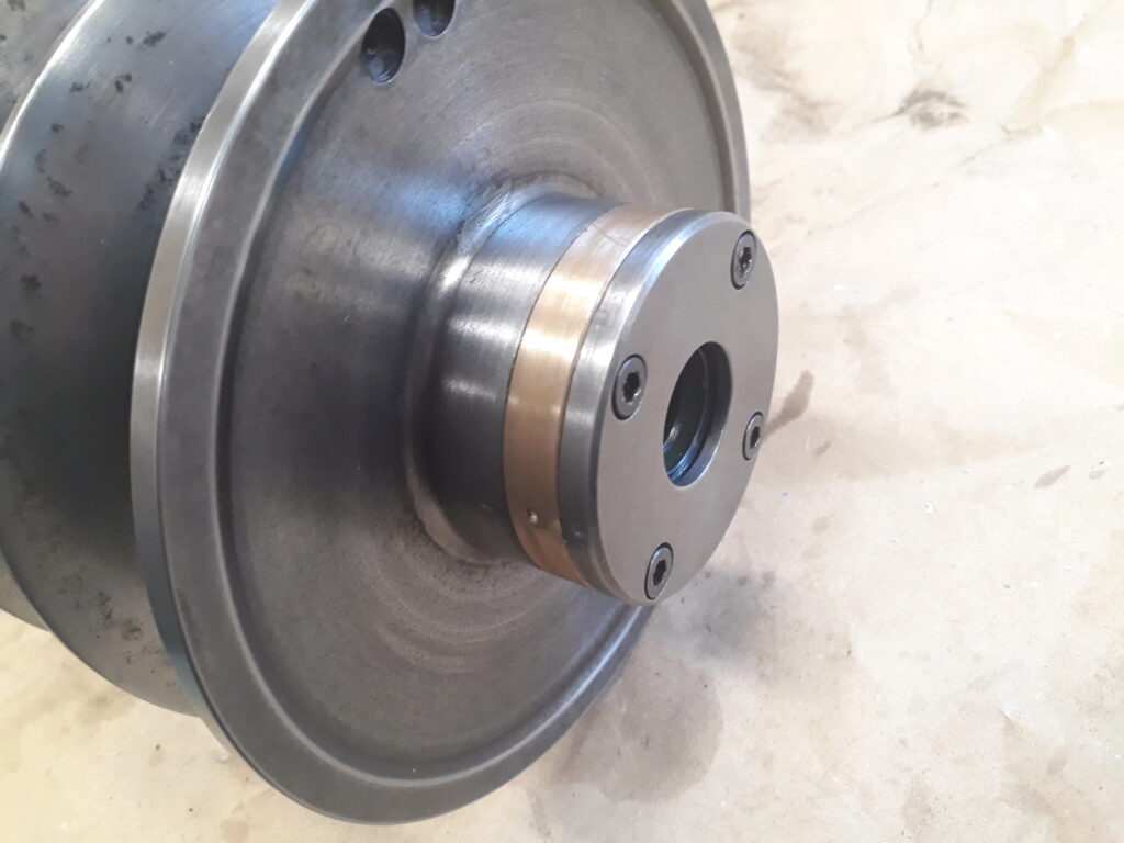
Finally, the result of mounting the pulley again is this one:
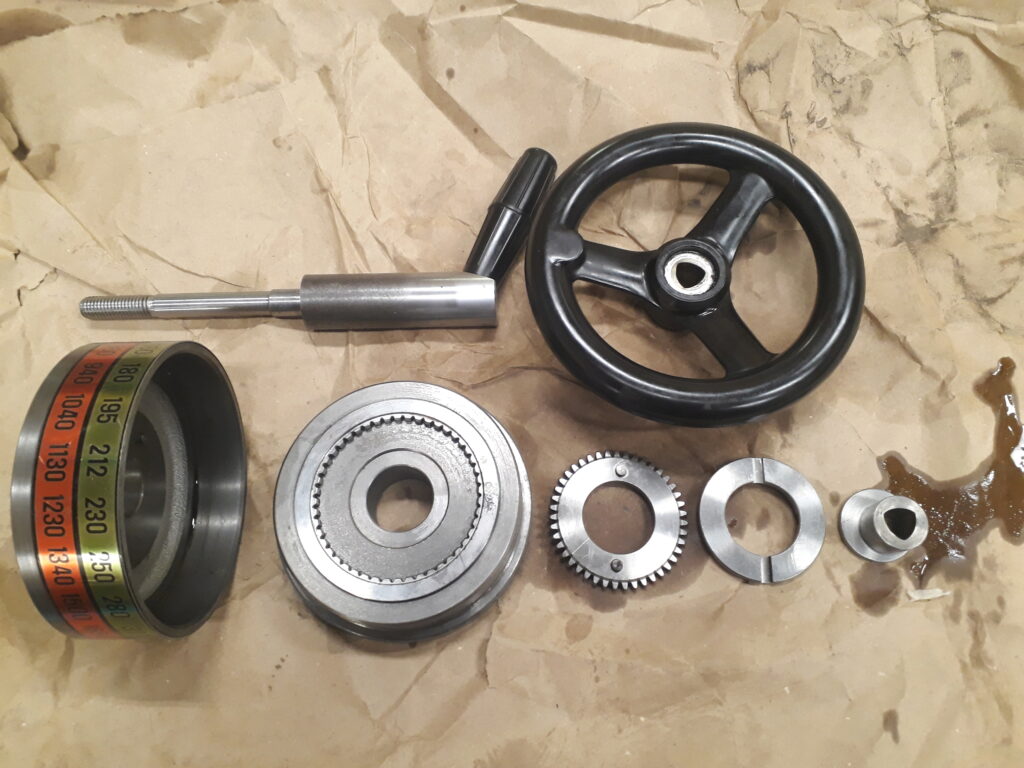
Speeds handwheel mechanism
Speed are selected by turning a handwheel. This handwheel ends moving up and down the middle pulley axis as said before. It’s interesting the very clever mechanism that turns the speeds indicator drum when the handwheel is operated. It is based on a planetary gear combined with a sliding collar that copes with the non centered movements of the planetary gear. It follows an exploded picture of this mechanism followed by a picture of the mechanism mounted on the machine.
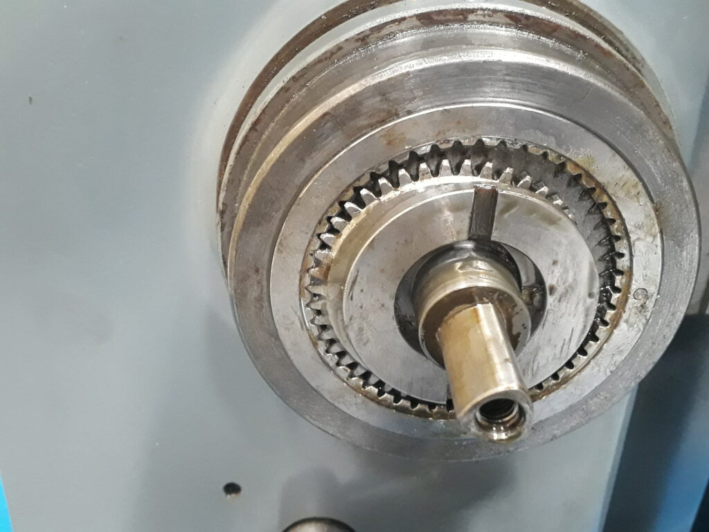
Note the polygonal profile of the shaft —usual on Schaublin machines. It seems to be a DIN 32711-1 P3G profile, which seems to be advantageous over more usual solutions.