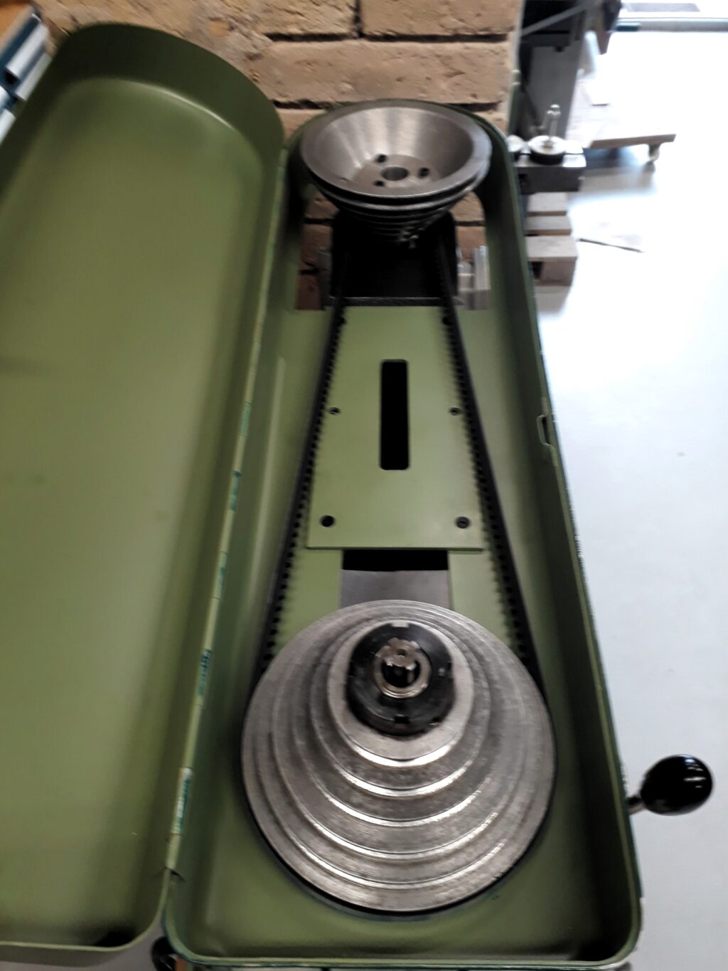
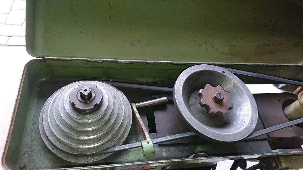
The drilling press was modified by a previous owner. As it can be seen in the picture below, someone added an intermediate pulley in the driving train to reduce the rotation speeds. What was the motor pulley became the intermediate pulley and a new single step pulley was fitted to the motor shaft. I have some doubts about the origin of this variation: would it be made at the Wörner factory after a specific requirement by a client?
Anyway, I was interested to recover the original two pulleys driver. I prefer this simpler arrangement considering that the motor will be driven by a VFD and thus a rich speed control will be available.
The plan was to bore the middle pulley and to fit a central core well suited to the motor shaft obtained from the actual motor pulley. Dimensions were carefully measured and some sketches drafted.
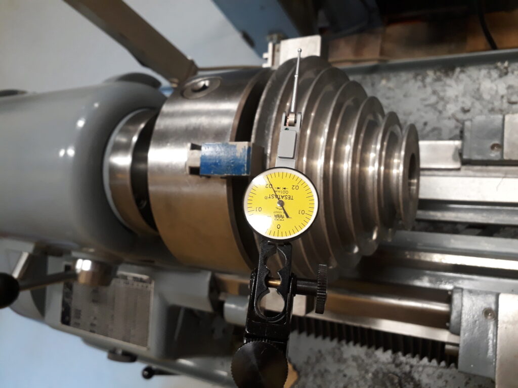
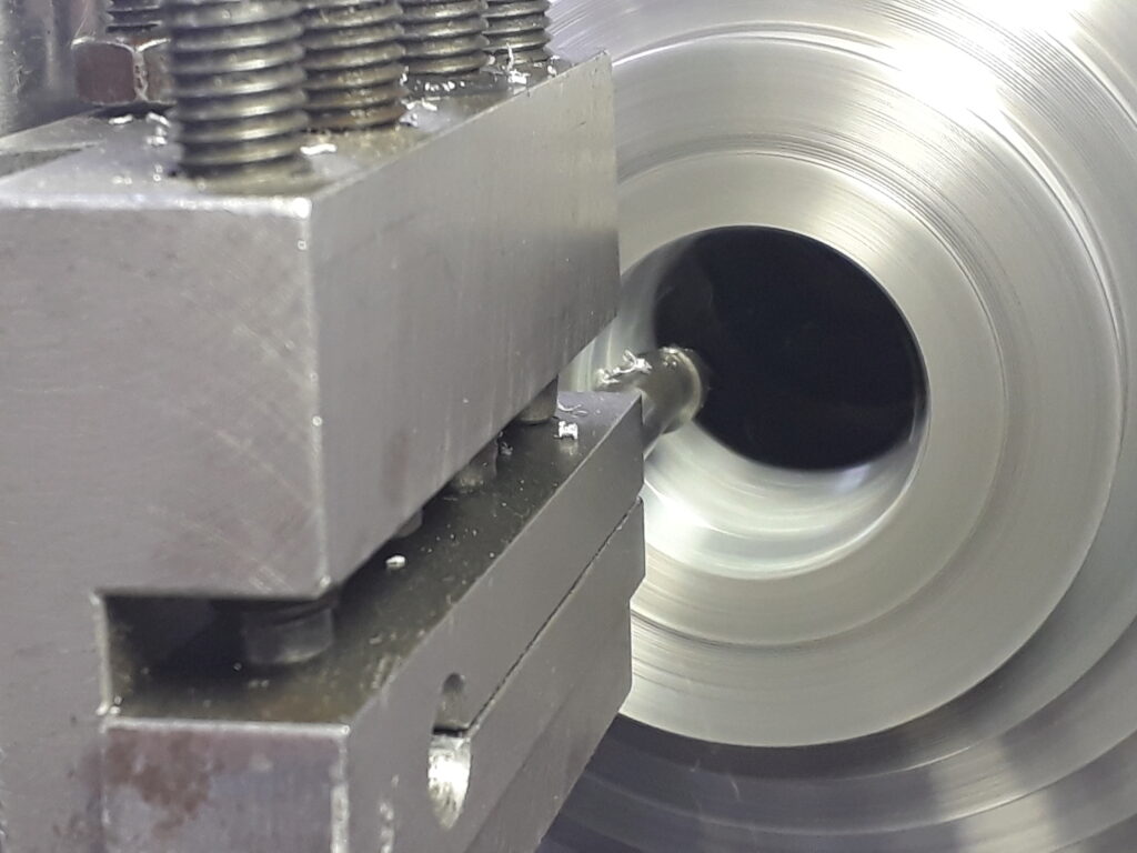
Work began by boring the pulley at the lathe after centering it carefully. Some pictures and a video follows:
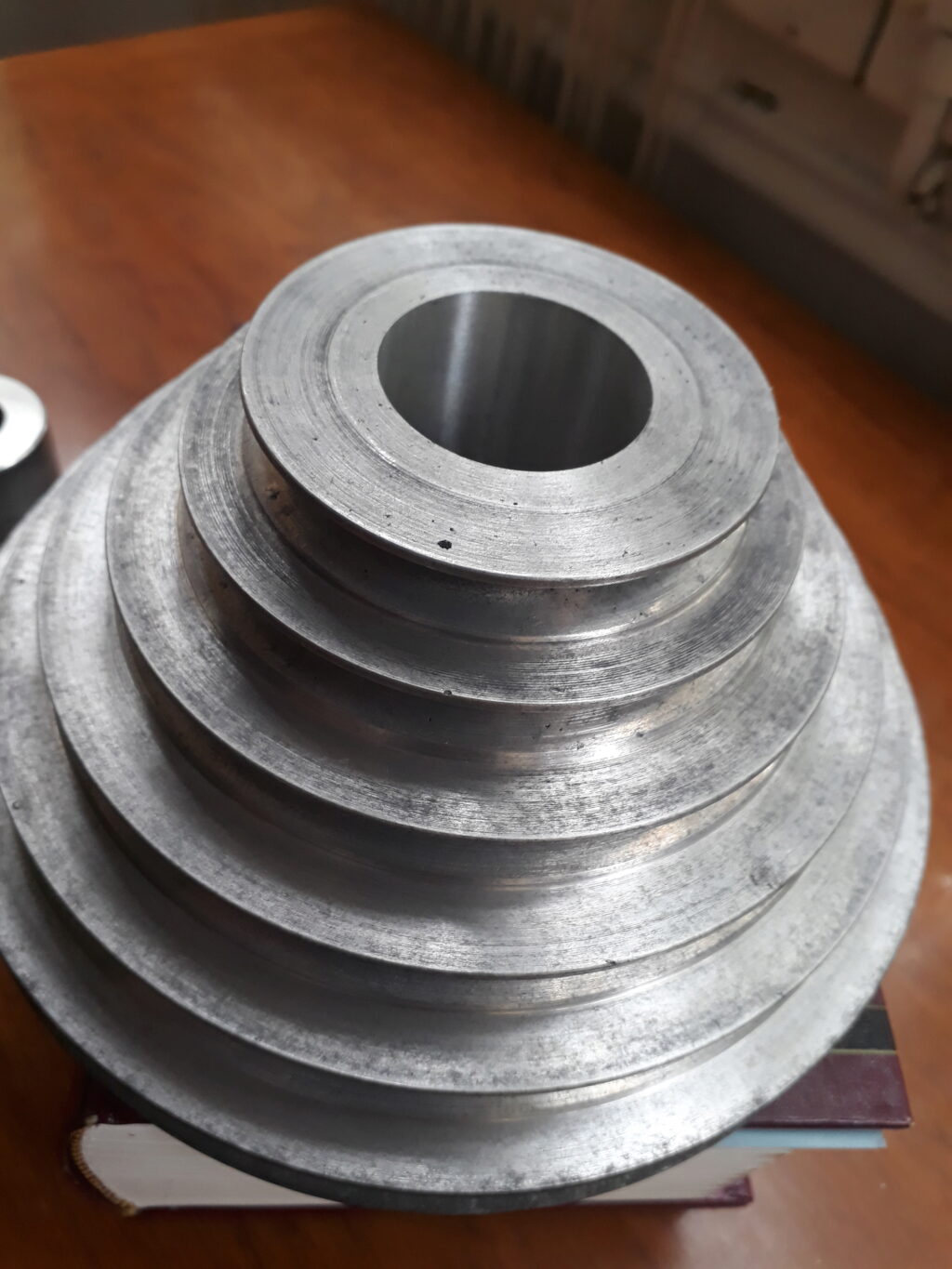
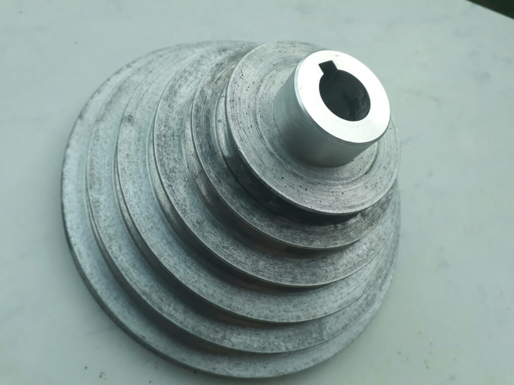
This is the finished pulley:
After that, the core was machined from the old driver pulley. Old pulley was first shortened using the chuck and, after that, it was turned mounted in a mandrel. Core was left 0.01mm over the pulley bore diameter. This was to allow a light shrink-fit between core and pulley. The pictures below show this process.
After that, the old driver pulley becomes as shows the picture (together with the bored pulley):
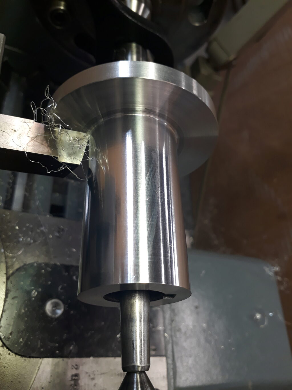
Now, it was turned to size mounted in a mandrel:
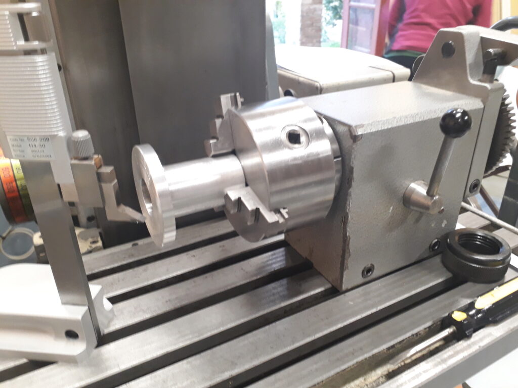
Next step was to trace and bore the three Allen screws that fasten the core to the pulley. This was done with the help of the milling machine divider as shown in the following picture:
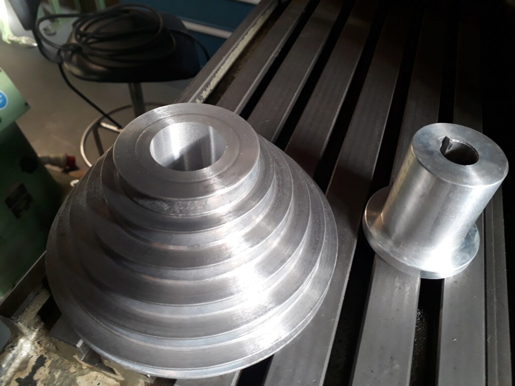
The finished pulley and its new core before fitting them:
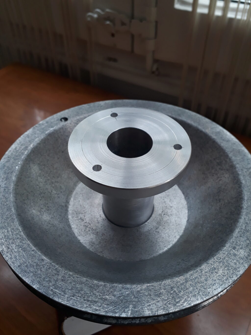
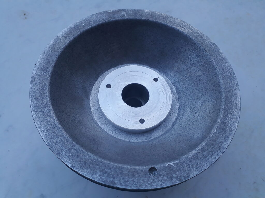
The core was fitted by heating the pulley with a hair dryer. This is the result:
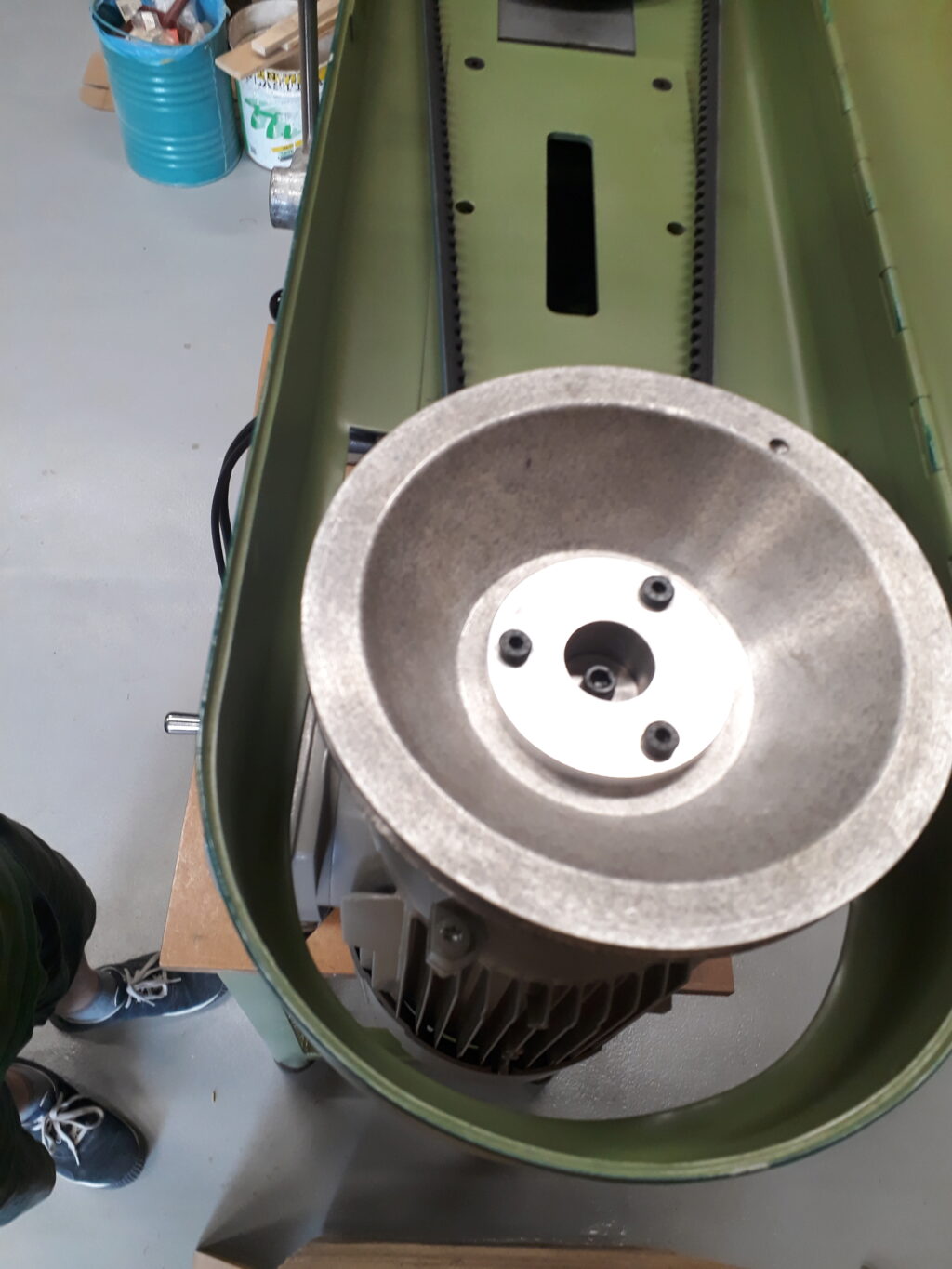
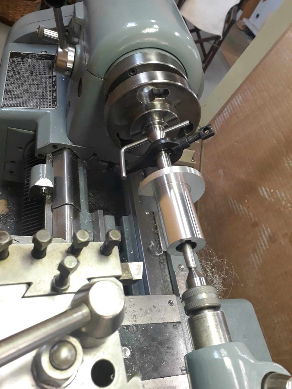
At the end, the new pulley system was remounted in the machine together with its cover. This is the result: