After being adjusted, the compound rest shows two issues:
- The motion screw exhibits a play that cannot be decreased. Provably the adjustable nut is severely worn.
- The crank has a fixed friction point when turning. No hints about the causes.
The compound rest has been dismantled and thoughtfully cleaned. First it was necessary to make a special socket wrench for the adjusting nuts of the compound gib. Next picture shows the wrench.
The following picture shows the parts that compose the compound rest:
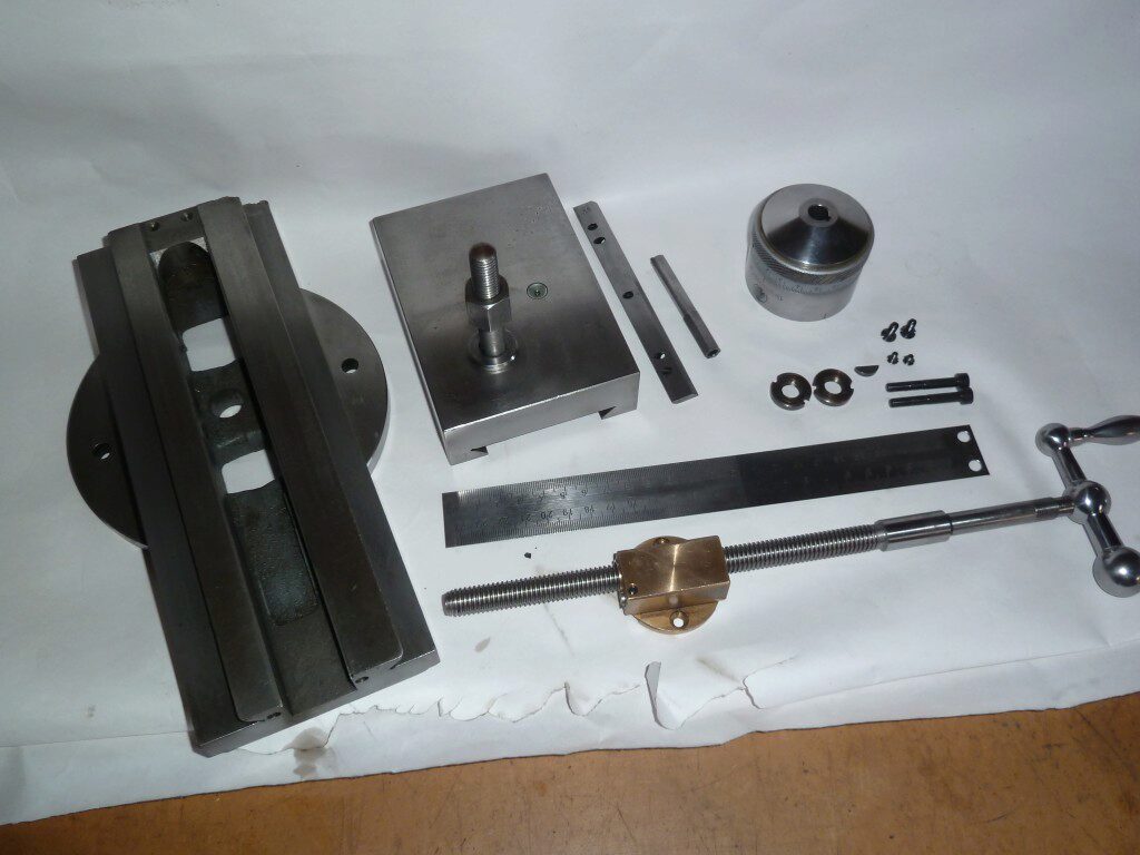
There are three notable things to remark about the beautiful build compound rest: the small adjustable nut; the gib, which is guided by a couple of pins instead of being guided by the adjusting screws as usual; and the design of the micrometer block. The following pictures show the details of these parts.
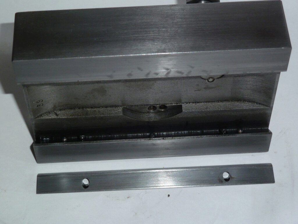
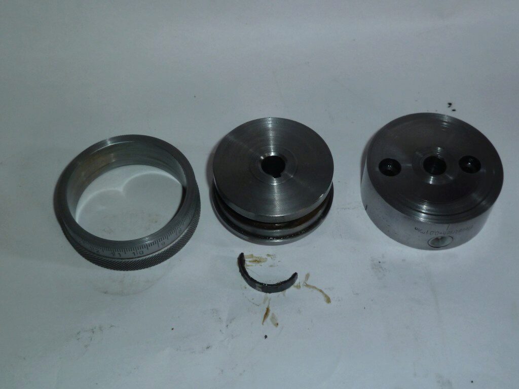
Note that the compound has a pair of pins that avoid the displacement of the gib and relieves the adjusting screws of this responsibility. The micrometer block discovers some marks which are produced by an uneven rotation of the motion screw.
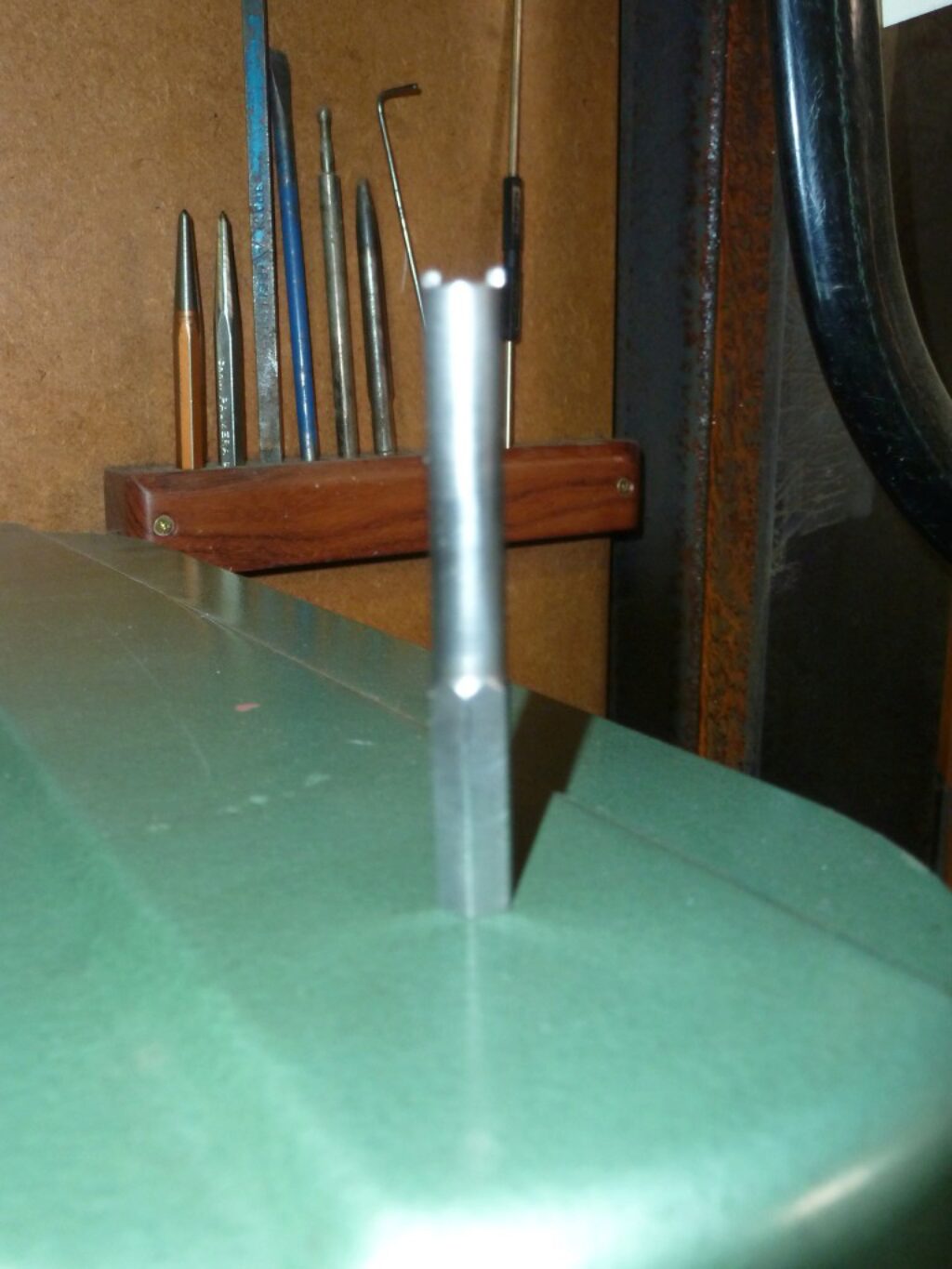
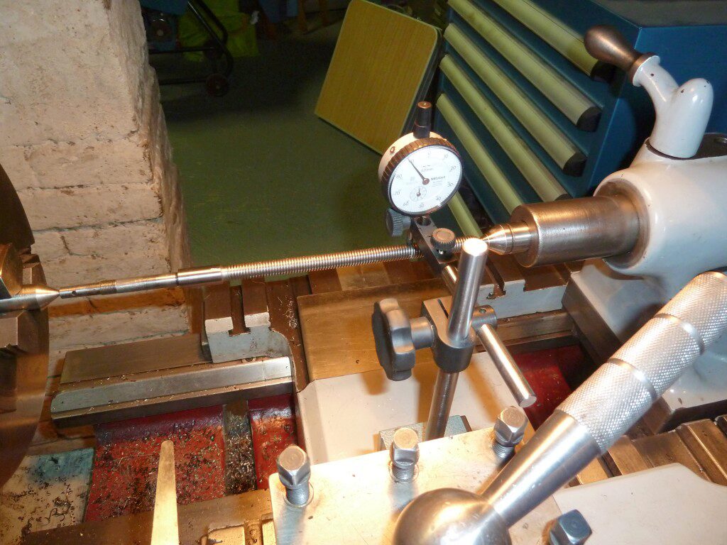
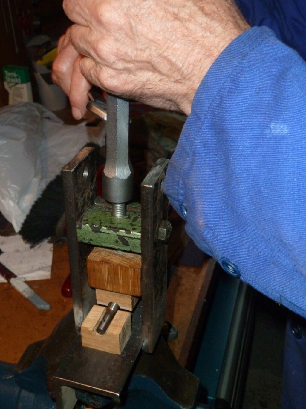
After analyze the screw we discovered that it is slightly bent. Possibly it is a consequence of an excessive thrust applied to it. We proceed to straighten it by mounting it between centers to measure the runout and correct it using a home made small press. Patiently using this procedure we achieve a maximum 0,05 mm of TIR. The following images illustrate the procedure.
We also repaired the adjusting nut, which was severely worn. The nut has two parts, one of them being the mobile nut. We made a new mobile nut to replace the worn one. After that it was possible to adjust the nut again.
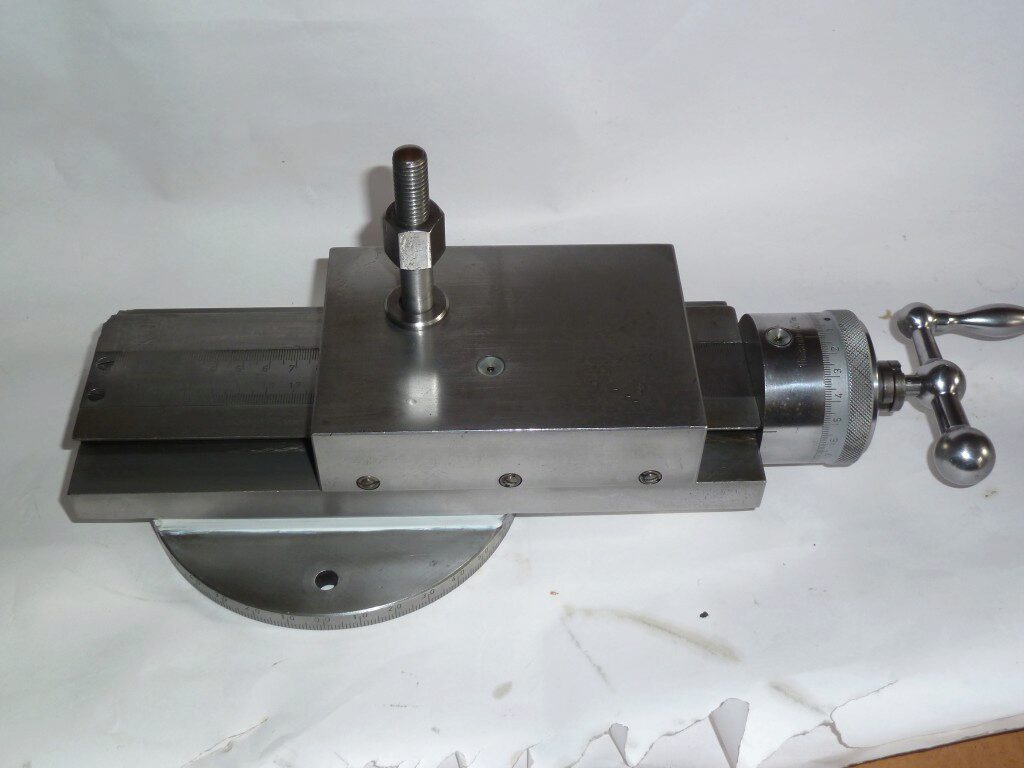
The compound rest was mounted again and adjusted. Now it has a very smooth and repeatable feel. The metal was cleaned with vinegar, dried and carefully buffed with a smooth buffing wheel and fine buffing compound. This is the result before painting it: