The contractor’s cabinet saw with sliding table S250 —made in Italy— was bought to the woodworking tools trader Miquel Martínez almost as scrap. The seller was really fair and honest and never tryed to hide the real problems of the machine. However, I was heavily interested in this given its dimensions and overall buildin quality.
Moving the machine at home was done by the seller itself. This machine is mainly built as a sturdy steel plate cabinet that supports a cast iron top where the 250mm saw tilting mechanisms are attached. The machine was clearly abused and some parts are obviously broken. The motor is burned as the selles told me. Overhauling it will be a nice project.
Saw state
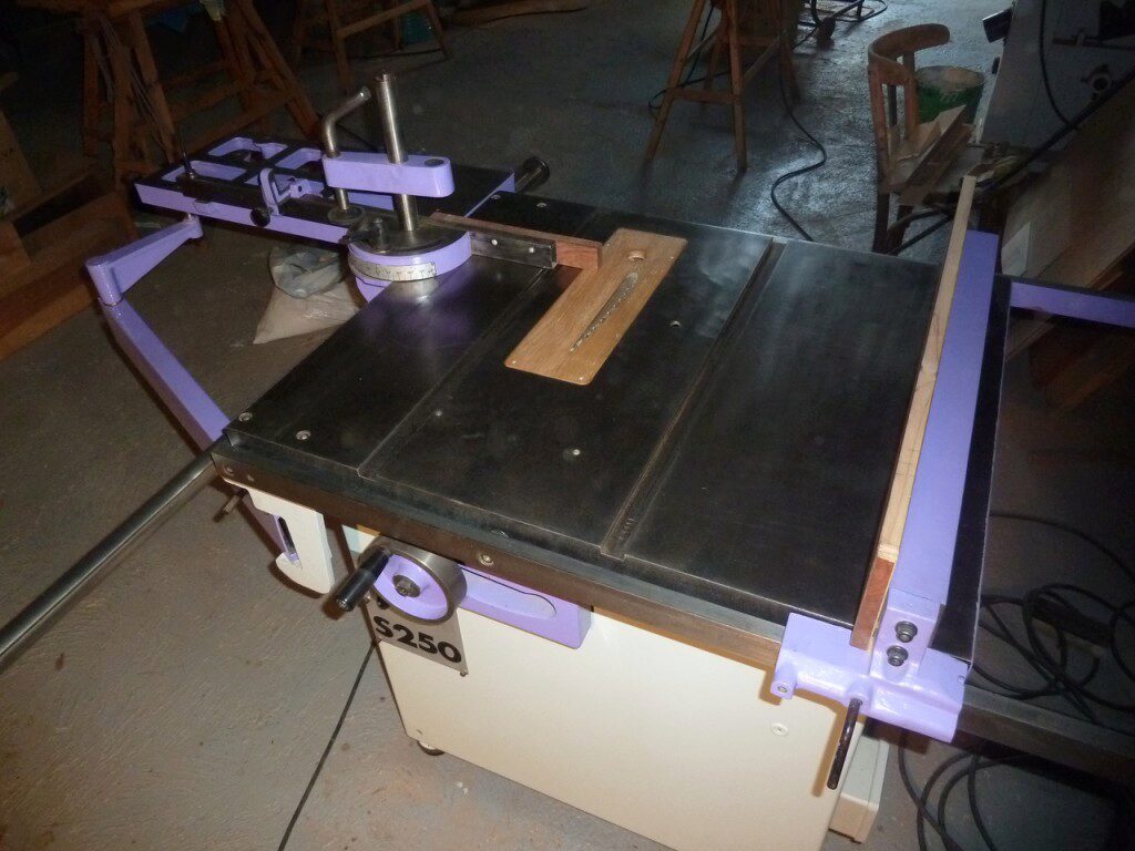
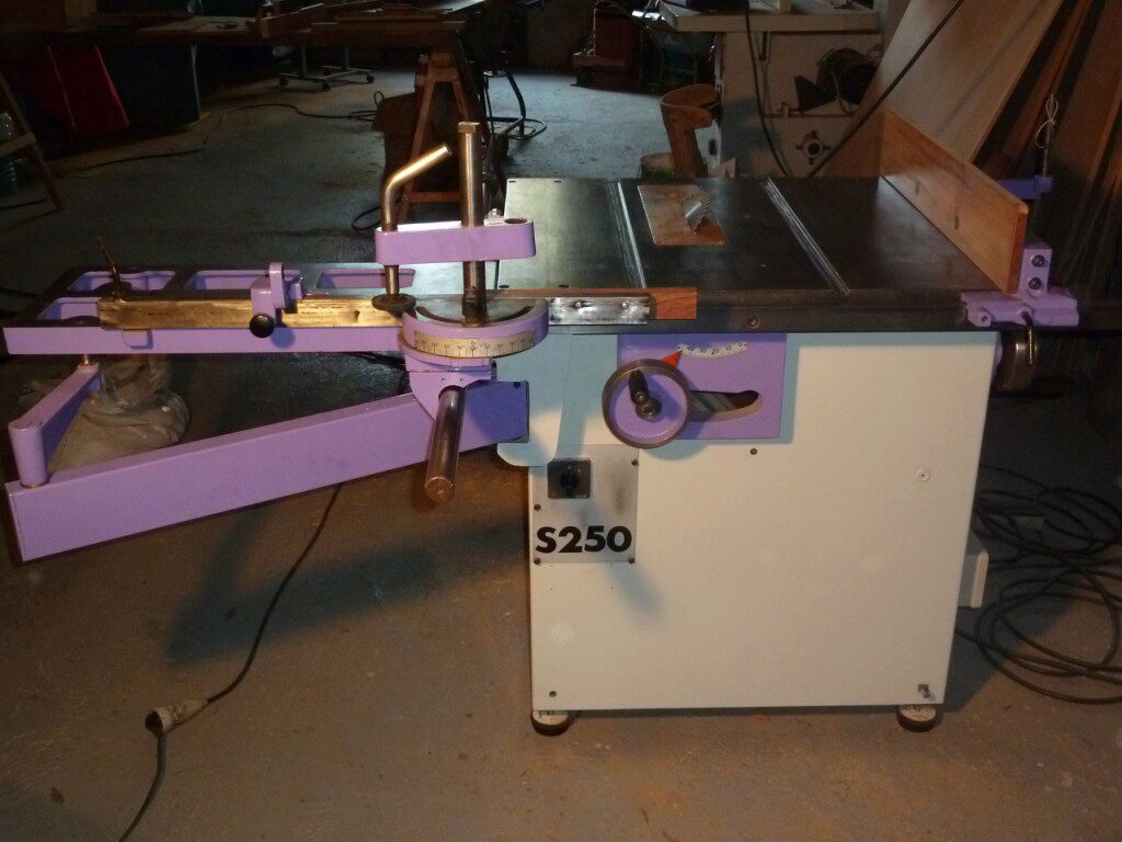
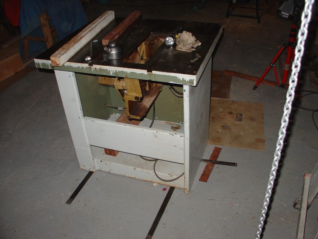
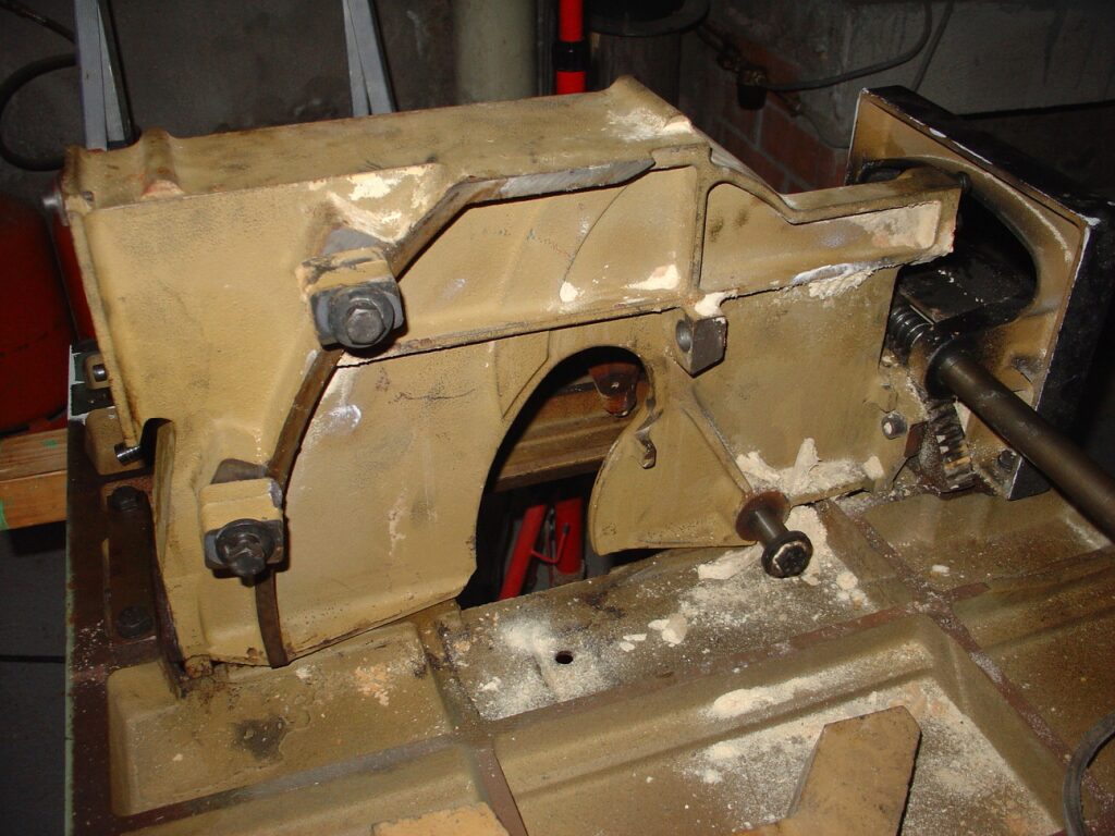
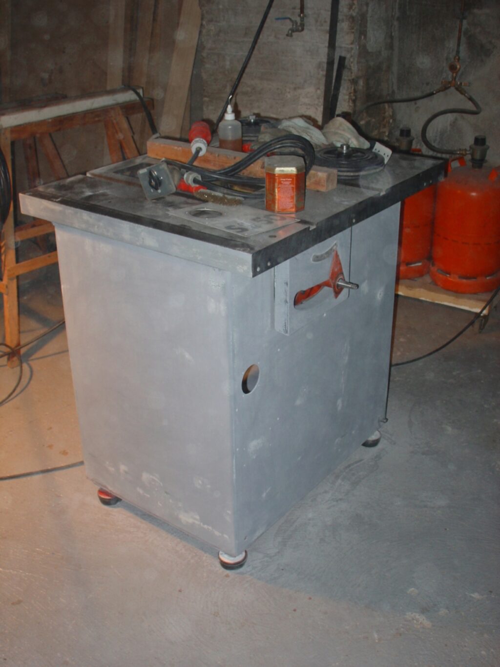
This is the saw looking when arrived at the garage:
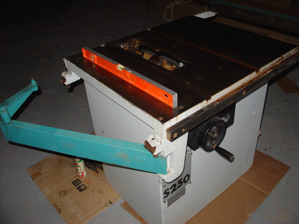
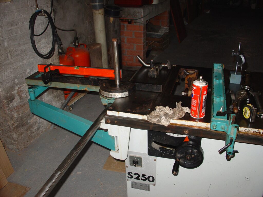
At first sight, the saw do not has major problems. A deep inspection after arriving home finds the following issues:
- Rust. The machine —as confirmed by the seller— was stored outside and after that it was subject to a supeficial cleaning. There are signs that it has been cleaned by using a steel wire brush and maybe a grinder. There remains, however, a lot of rust to be treated.
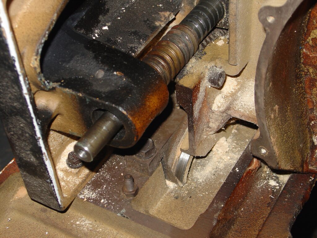
- There is not one of the turning handles. That of the saw tilting shaft.
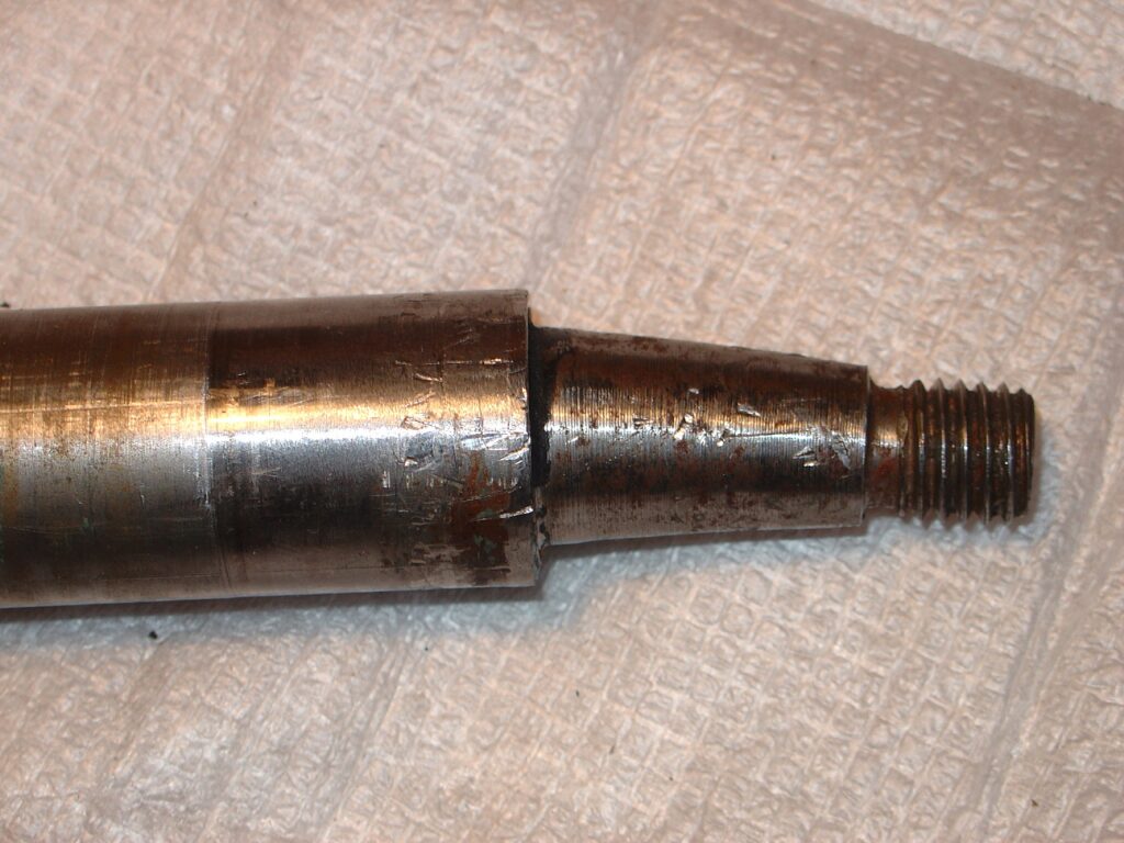
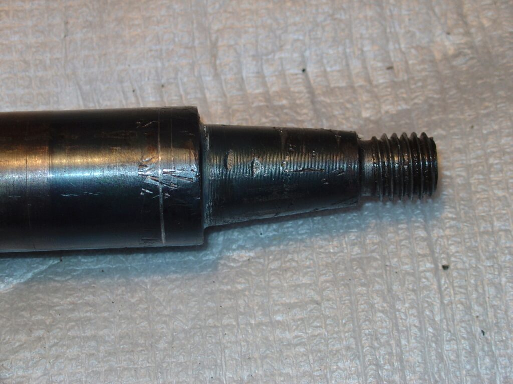
- The tapered end of the missing handle shaft is bent. It seems that it received a strong blow that broke the handle and bent the shaft.
- The fence support was broken.
- The motor was burned.
- The sliding table supports were broken. The sliding table is supported on a shaft through a couple of sliding supports. These supports were broken.
- The electrical wiring is in bad state.
Dismantling the saw
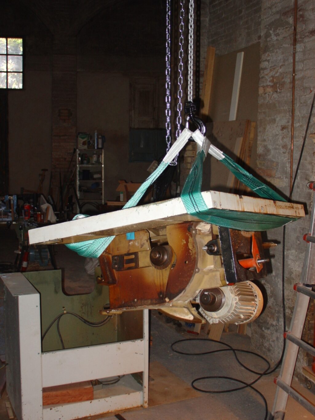
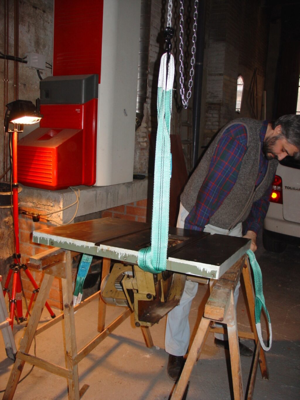
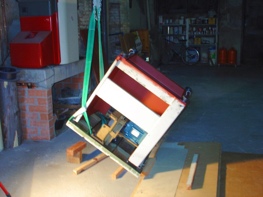
I first dismantle the machine. The saw, which is rather heavy, is moved using a chain hoist and using greased flat bars to slide it over. See the next picture.
Helped by the hoist, I take out the saw table. The table is bolted to the cabinet with rubber washes between both parts to compensate for deformities. The table is turned over a couple of sawhorses.
Next, the saw moving mechanism is taken apart and cleaned. I separate the motor and the saw shaft. The saw shaft bearings are replaced.
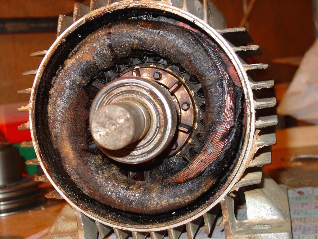
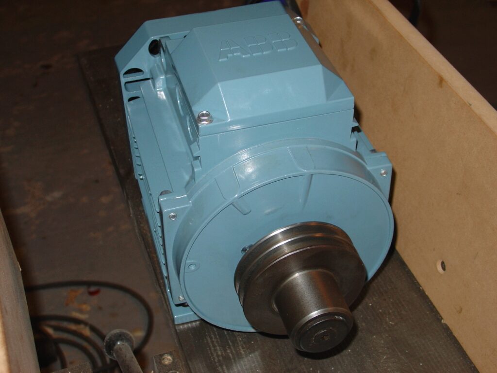
Motor
Motor was burned as the seller told me before. A new ABB motor and a set of new belts where mounted. The pictures below show the original (italian made) motor an the new one.
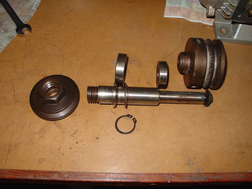
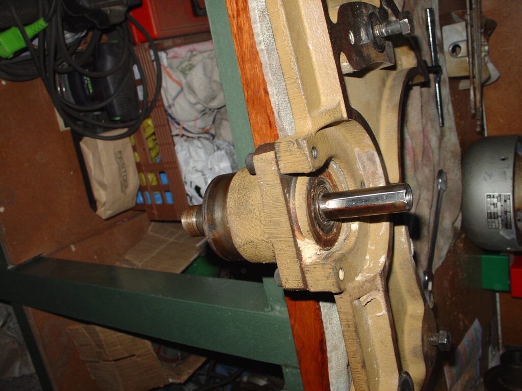
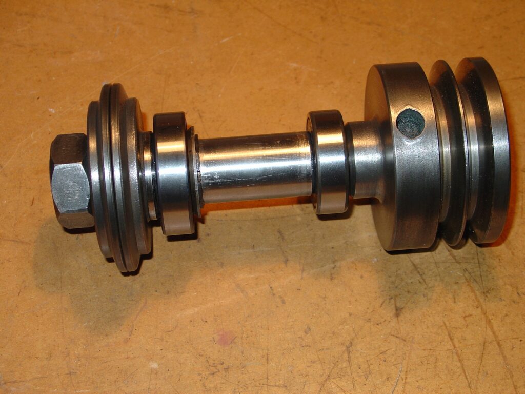
The saw shaft
The saw shaft was supported by two closed bearings. I replaced them by a couple of new ones. Next pictures show the saw shaft in distinct phases.
Shaft lock bar
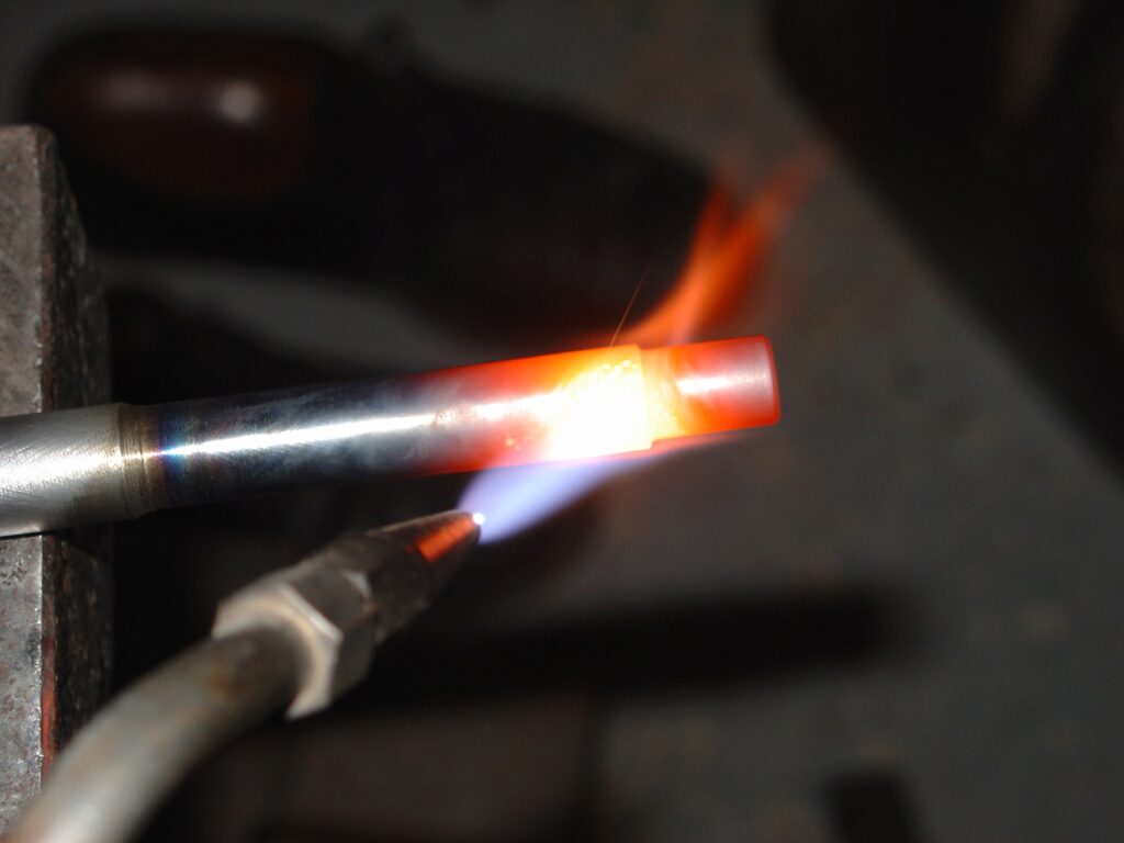
To lock the saw shaft when you change the saw blade you should use a specific bar that fits some holes over the shaft pulley. I turned a lock bar from steel and heat treated it using the oxiacetilene blowtorch. The following pictures illustrate this process.
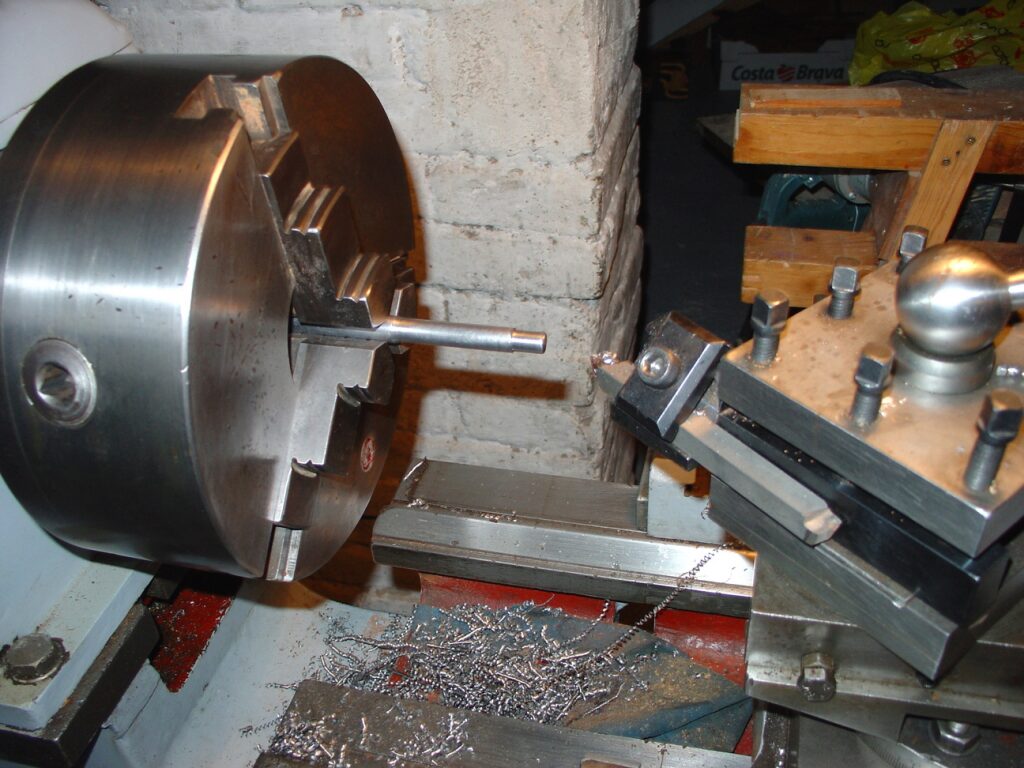
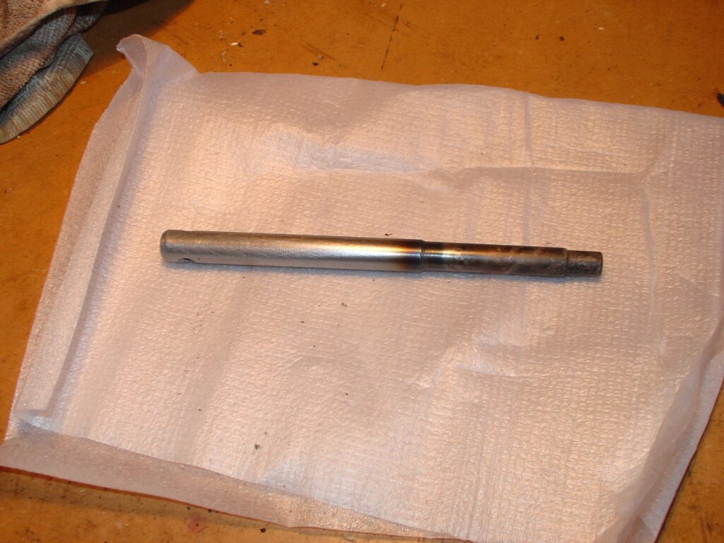
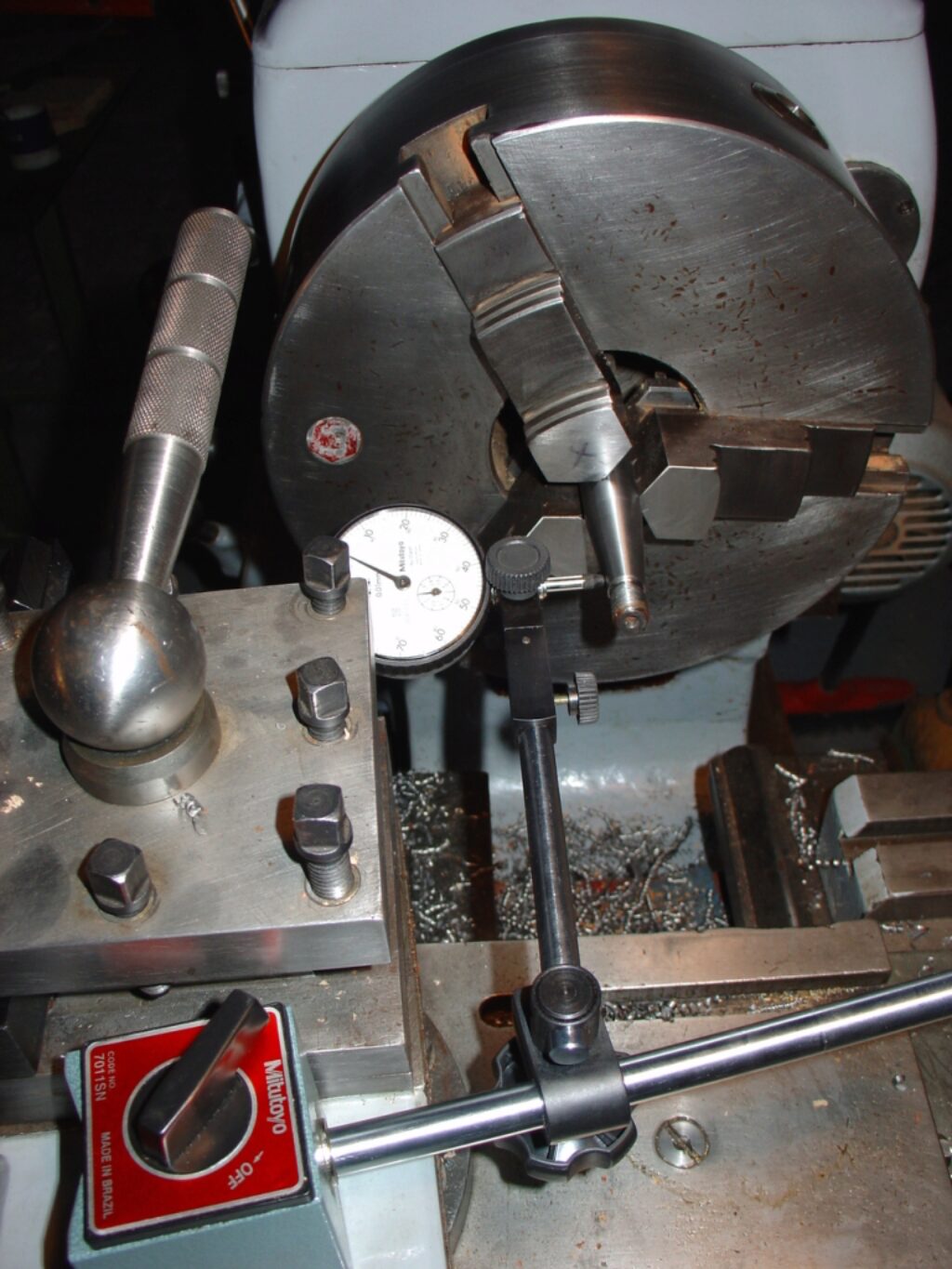
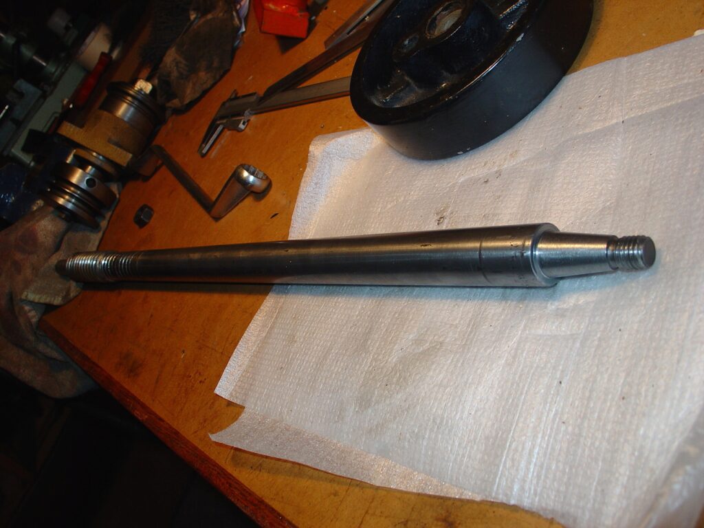
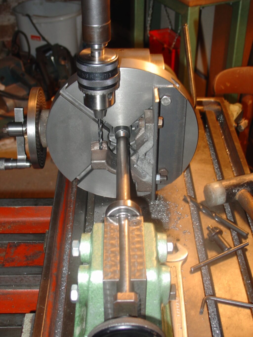
Repair the tilt handle shaft
The tilting handle shaft protrudes at the left of the cabinet but there is no handle there. Just a bent shaft tappered connection appears in place. It seems that an important blow had broken the handle and bent the axle. The handle should be of cast steel not unlike the blade elevation wheel. I first repair the shaft. I try to straighten it by heating it and hammering it straight again on the anvil. Then, I turn it perfect again with the same geometry that the elevation shaft. See the next pictures.
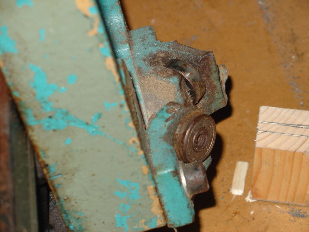
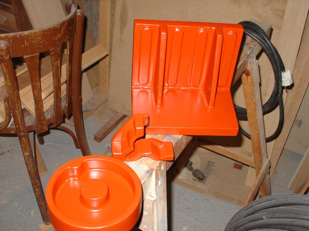
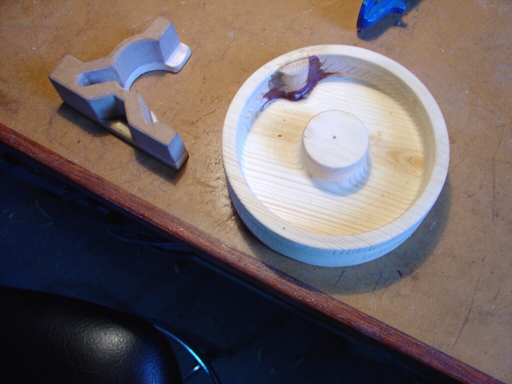
Sliding carriage supports
The saw carriage moves over a steel roun bar supported by a tunnable bearing based supports. The two supports are cast iron and are broken. There ara traces of having been welded time ago. Thus, they should be broken several times. To overhaul these supports will be the most complex task of all the project.
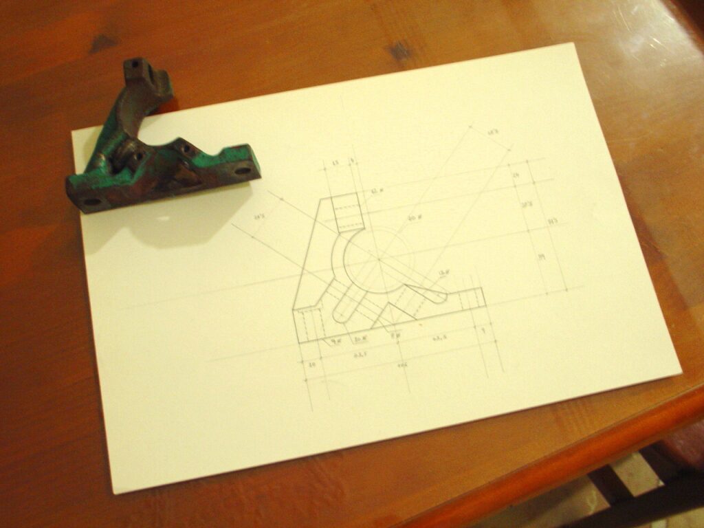
I first made a carefull blueprint using the parts remaining. After that a wood pattern was made to cast a new set of supports. Casting was done at Fonería Martínez. After that, parts should be precisely mechanized on the milling machine. Next pictures document all this process. Note that it will show also the pattern for the missing tilt handle.
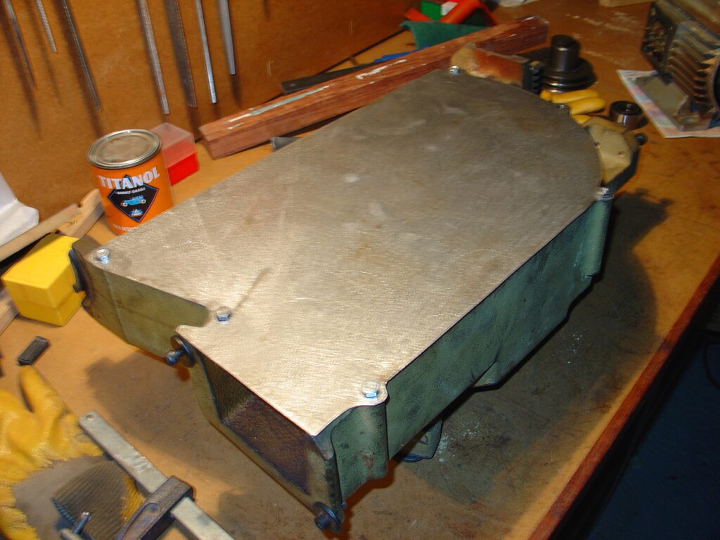
Blade box cover plate
The blade box cover plate was missing. I cut a new one from steel plate.
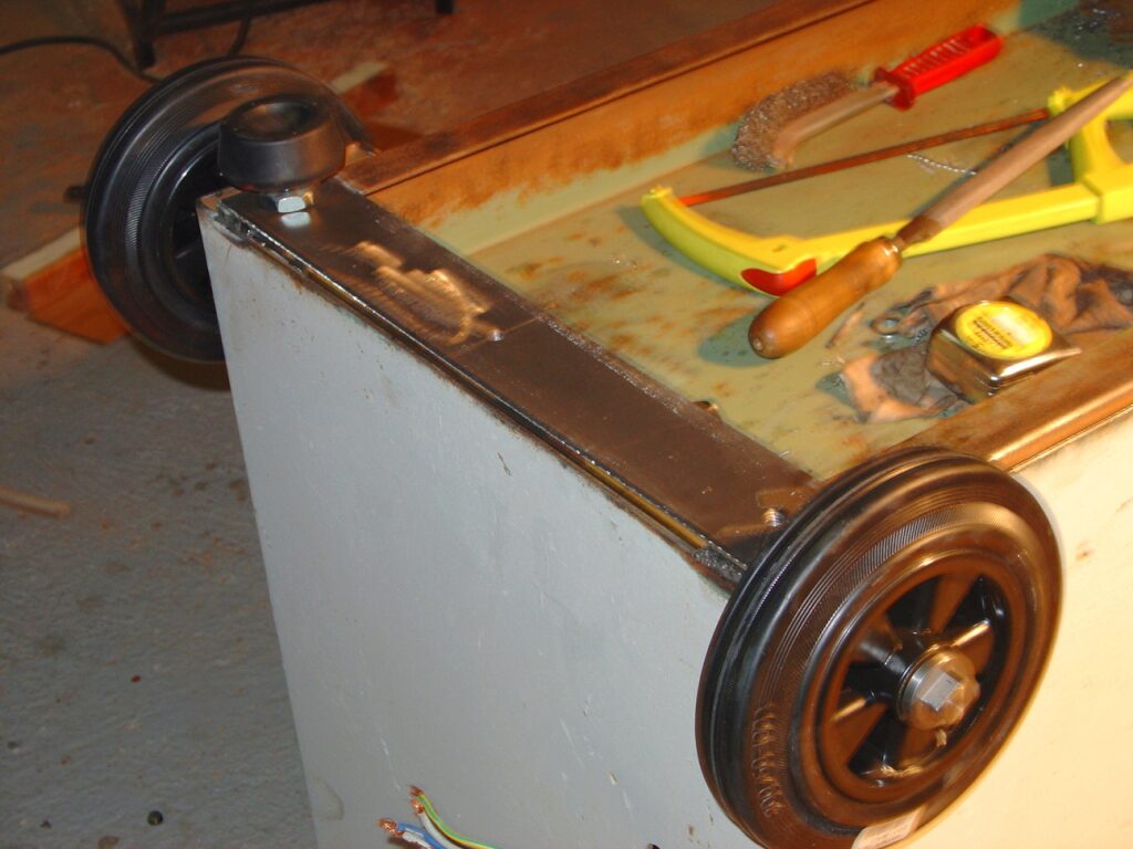
Feet and wheels
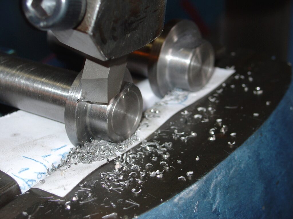
We add rubber feet and wheels to make easier to move it. The wheels shafts can be screwed in and ou to allow wheels to be removed easily. In the pictures you will see the shaper cutting some flats to the wheel shafts.
Finishing and paint
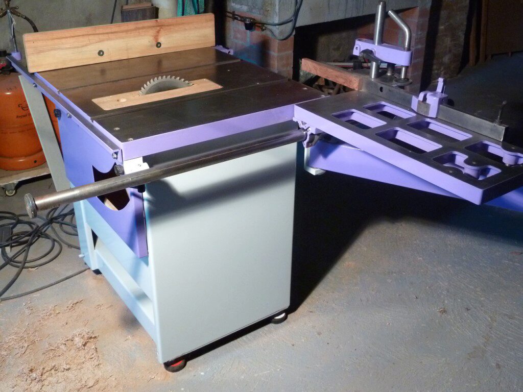
Finally, the machine is derusted and the old paint scraped. New painting process includes applying primer, sanding it, and lackering with two colors. This ends the project with an fully operating machine.
This is the finished machine, It works like a clock. It’s stable ans precise. A pleasure to work with.